As I already explained in the previous posts, basically Fuelino increments the fuel injection time by a specific period (defined in %), based on how the calibration maps are set (using the calibration tool). In particular, the maps are 2: one map defines the increment (%) depending on the engine rotation speed (rpm); the other map defines the increment (%) depending on the Throttle Position Sensor value (10 bits, 0-1023). The injection time increment percentage is the sum of the values calculated based on these 2 maps. A deeper explanation is available at this link.
Today, I will focus the attention on the first map, which is called incrementi_rpm[] inside the SW. In this map, there are 8 calibrate-able elements (%), each one referring to a specific break-point (rpm). Practically, in order to reduce the calculation burden (Atmel ATmega328p cannot perform divisions quickly), I decided to use the "delta time" between 2 injection starting points, as break-point, instead of rpm. These values corresponds to the time ticks (4us) measured by Timer1 between 2 engine rotations (2 consecutive injections), and it is inversely proportional to the engine rotation speed (the more the engine rotates fast, the less time is required to perform 2 rotations). For example, at 1200rpm, engine performs 2 rotations in 100ms, so the Timer1 will measure 25000 ticks; at 12000 rpm, Timer1 will measure 2500 ticks only.
Once each injection is commanded by the original ECU (for example, Keihin on Honda CBR125R), Fuelino calculates the "delta time" (2 engine rotations) between the present injection and the previous one, and checks, using incrementi_rpm[], which is the proper injection time increment (%) to use. Each element of the map is 1 byte (0 = 0%, 255 = about 50%), and can be calibrated using Serial connection with Fuelino Calibration Tool. For "delta time" measured values between 2 break-points, Fuelino uses linear interpolation, to calculate the proper increase percentage, as shown below. The graph below shows the increase (%), incrementi_rpm[], which is a function of "delta time" (time between 2 injections), which is inversely proportional to the engine rotation speed (rpm). The inverse proportionality to the rpm is the reason why in the following graph, between 2 rpm breakpoints, the mathematical curve is hyperbolic, and not linear (as should be for direct proportionality). Also, in the following graph, the thin curve shows the theoretical curve, while the blue circles show the empiric data measured when feeding Fuelino input with a simulation signal, and measuring its output command with Pico DrDaq. As you can notice, there is a pretty good correspondence. It must be noticed that, from theoretical point of view, for each calibration point, since 1 byte is used (to reduce RAM consumption), and since 256 would theoretically correspond to a 50% increment, the calibration resolution is 0.195%. Other small errors might be caused by interrupt execution timings, and so on, which affect the injection time accuracy, in relative terms, especially for low injection timings (example: 10us error at 500us pulse is 2%, but at 5000us injection pulse it is just 0.2%).
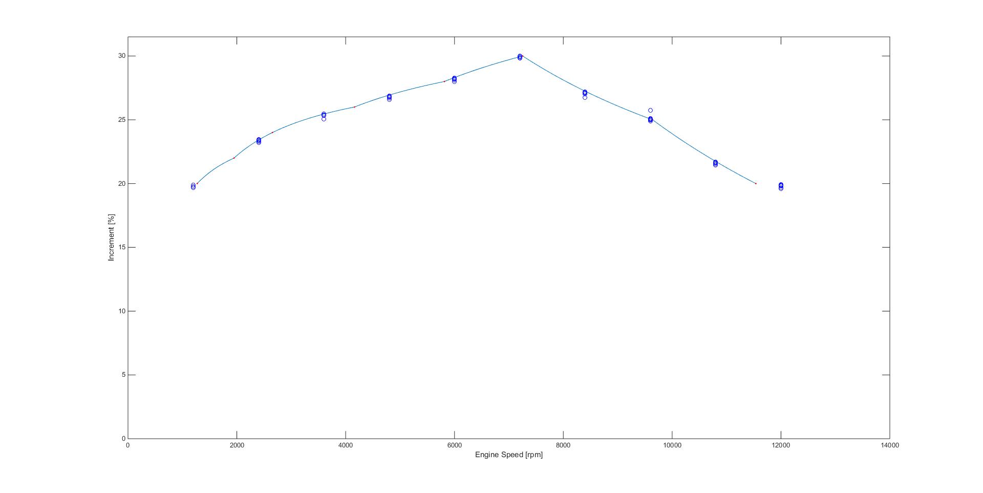 In order to perform the validation activity of the maps interpolation algorithm, I used Pico DrDaq to feed Fuelino with a probing injection signal (simulating the original ECU), and at the same time I acquired the injector command signal output by Fuelino. I created a fully automatic tool for that purpose, using Visual Studio 2013 and Pico DrDaq libraries. The tool feeds Fuelino with many injection signals at different rpm and injection periods; then, it measures Fuelino output command period, and determines how much is the percentage of increment that Fuelino is outputting. All empirical data is available here: 20170111_incrementi_rpm_export, and the measured points are shown in the picture above, as blue circles, as well as in the screenshots below.
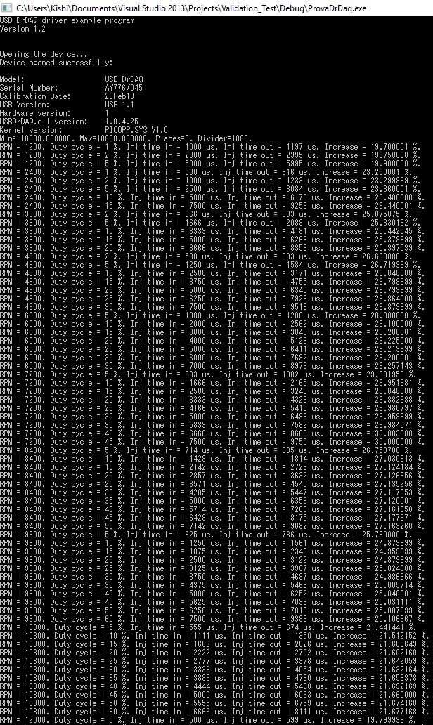 Empirical data obtained. This is the report (CSV file) automatically generated by the validation tool.
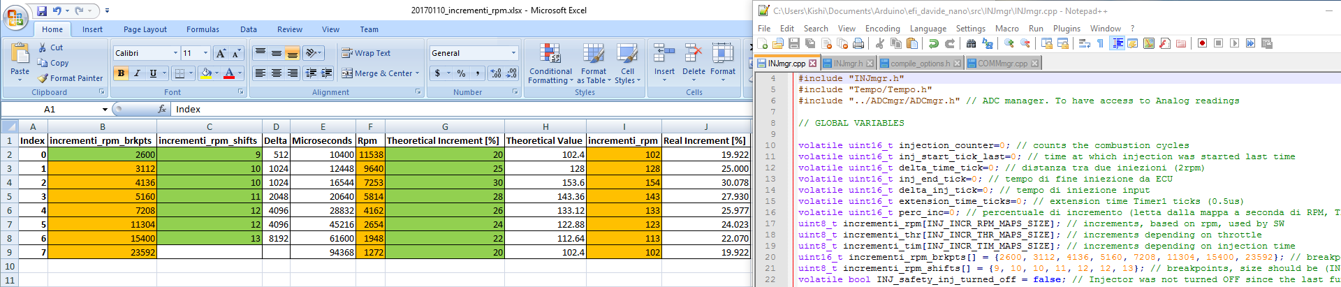
 The map breakpoints (Timer1 ticks) are fixed inside the software (as "consts" values), and a modification needs to compile the software again. However, it is something that rarely has to be performed. You can use the standard breakpoints, unless you want to personalize them. In order to simplify the division (ATmega 328p cannot perform division operation), and transform it into a simple bit shifting operation, there is one limitation: the distance between one map break-point and the next should be a multiple of 2. Doing so, when interpolating, the division by "delta x" (distance between 2 breakpoints) becomes a simple binary bit shifting operation. I also created an Excel file which may help, in the extreme case in which you would like to change the breakpoints: 20170110_incrementi_rpm_breakpoints.
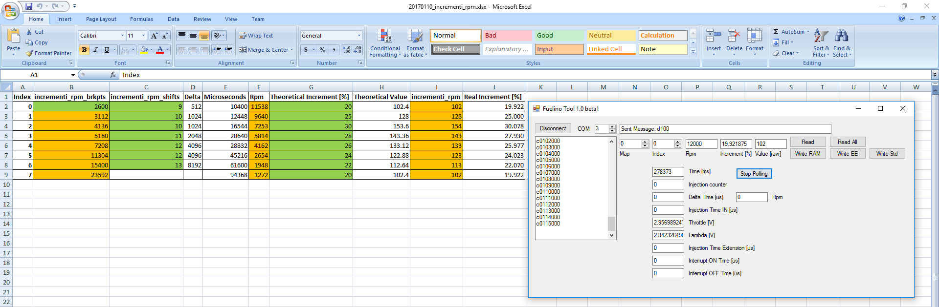
 After deciding how much you want to increase the injection time (%) for each "delta time" (engine speed, rpm) break-point, all you need to do is to write and test these values into Fuelino, which is very simple: using Fuelino Calibration Tool, via USB serial communication protocol, it is possible to read and write the calibration maps written in Fuelino, as visible in the screenshot below (right side). Each calibration change is at first memorized only in RAM memory ("Write RAM"); in order to write the complete map into the EEPROM, so that it will still remain after power OFF, you need to click on "Write EE". I implemented this rule in order to avoid writing too many times on the EEPROM, since it reduces the EEPROM lifetime. You should at first try new calibrations "on the fly", by saving them in RAM memory. Once you are sure about the calibration map (they are working well on your engine), you can click on "Write EEPROM", and the calibration map will be stored permanently in the EEPROM.
 Now, the question is: "how do I calibrate the maps"? The answer is complicated. You should have at first a "starting point" idea. For example, in my case, I upgraded from 125cc Honda original cylinder, to a 166cc Athena bore up kit. Therefore, since roughly 30% more air will enter the engine (at full throttle open), you should set a similar fuel increase percentage (30%) as tentative value. Practically, this value will not be good for all rpm, and for all throttle values. I expect that, for example, at high rpm, the air intake efficiency will be slightly lower, for example only 20-25% more, due to pressure losses (the intake duct and valve size did not change). And also, at low throttle, I would expect a lower increase. You should play with the values in the map(s), and check the engine behavior, color of the smoke (white = too much air, black = too much gasoline), and tune your motorcycle until it has the best performances. By the way, you don't need to be very precise, since the original ECU (example: Keihin on CBR125R) will still have "close loop control" active, which is using the lambda sensor signal to correct the fuel injection time; therefore, even if you make a small mistake, for example + or - some percentage points, the original ECU will cover this error.
例ですが、元のECUがレブリミットで10000rpmでインジェクタ出力がOFFになるECUにFuelino Proto3をつけることによって10000rpm以上でもインジェクタ出力がONになるようには出来ませんか?
可能であるなら配線図や、プログラムなどのアドバイスがほしいです。
こんばんは。Fuelinoのページをご確認ください。
配線は変わりません。回転数は噴射時間に限られています。
例えば、噴射時間が10,000usなら、最大回転数は12,000rpmです。
ご返信ありがとうございます。
私のECUは9500rpmで噴射時間が約4msで10000rpmになると0msで噴射しなくなり、リミッターが効いてしまいます。
Fuelinoを多少修正することにより、10000rpm以上で噴射時間がECUから0msでも噴射できるようにはできませんか?
また、Fuelino Proto3のプログラムを修正して、2インジェクタの入出力を使い、点火を管理できませんか?
Fuelino Proto3ほんとにおもしろいです!
返信感謝します!
あh、わかりました。
リミッターを消したいですね。
残念ながら、FuelinoはECUからの信号を受けないと、噴射しないので、結局10000rpm以上は噴射できない。
ちなみに、どのエンジンを使っていますか?何の改造をしていますか?
純正のエンジン(改造なし)だと、リミッターを削除する意味がない。最高パワーは上がらないし、エンジンを壊す可能性もある。
(回転数を上げすぎると、摩擦が上がる、熱が上がる、エンジンがオーバーヒートで壊れる)
返信感謝します。
シグナスとjogにFuelino を使わしてもらってセッティングしてます。
4stシグナスはエンジンは180cc、冷却系は強化し、ヘッドも変更してバルブスプリングも強化してあり、その他変更しており回転数には耐えれる様にしてます。
4stJogも同じく100cc ヘッド交換その他も交換しており、燃調は楽にセッティング出来ているのですが純正EUCによるリミッター&点火遅角が邪魔になっています。
どちらも配線に関しては分かってはおり、Fuelinoを接続しています。
CBR125ではないので他のバイクによるプログラムの変更(スロットルのV)はしていませんが…
シグナス、JOGはほとんど同じECUなので配線も似ていて、噴射リミッターは9800rpm、点火リミッターは11500rpmまで信号がある事は分かりました。(燃料噴射さえできれば11500まではリミッターが効かなくなるはず)
可能であれば、クランクポジションセンサーからの信号を元にRPMを判断&点火や燃料噴射出来れば良いのですか…
配線&エンジンは大丈夫ですが私はプログラムが全然出来ません…
アドレスよろしくお願いします。
感謝します。
I would appreciate it if you could reply to me.
やりたいことは理解していますが、SW変更が必要となります。まず、オシロスコープなどでバイク側の信号のタイミング、波形などを確認する必要があると思います。その後、その信号に合わせたハードウエア、ソフトを作る必要があります。
最近は、お仕事が忙しいですし、バイクも変わったし、Fuelinoを使う機会が全くなくなりました。
コードはこのウエブサイトでみんなダウンロード出来ますが、私はサポートをする時間がないので、ご理解のほど宜しくお願い致します。申し訳ないです。
コメント失礼します。
噴射時間増分(%)は0 = 0%、255 =約50%とありますが、-%にすることは出来ませんか?
大容量のインジェクターを取り付ける際、マイナスに設定したいです。
すみませんが、マイナスは不可能です。
sorry to join chat above. i have "piggyback" from my country
it can reduce injector flow from original ecu signal , start from -20%, and can add more fuel 30%
and this piggyback can "remove" injector limitter ( not remove in actual), it just capture or take the data just before the original ecu limit comming up, and copy the signal and use to rise up the limitter. it can be adjust just by vr (variabel resistor)
and the piggybak it self is not programable for the user. it just use 3 vr to setting, to reduce or add more fuel,
vr 1 is use to low range rpm, vr 2 to use at mid rpm, and vr 3 is for high rpm set, ussualy the set is vr 1 at 0-3000 rpm, vr 2 at 3000-7000 rpm, and vr 3 at 7000-limitter,
and for 1 device it just use 4 vr to adjust
if you dont mind, i will send you the pic to your email.
thanks a lot before .