Today I would like to share with you the schematics of the DIY ECU which I built for my Honda CBR125R. This additional ECU does not have the purpose of substituting completely the original Honda (Keihin) one; it is an ECU which works, in series with the original one, to manage the signal of the fuel injector. The purposes of my project are as following:
- Measure the injection time of the original ECU;
- Adapt the injection time (increasing it or maintaining it as it is), by means of a "man in the middle" operation between the original ECU and the injector; this signal is supplied to the original fuel injector;
- Measure the time between 2 consecutive fuel injections, in order to estimate the current rotation speed of the engine (each injection happens every 2 crankshaft rotations);
- Measure the throttle position sensor voltage (TPS signal from 0% to 100%); this signal varies in the 0V-5V range, according to the Honda CBR125R Service Manual;
- The above info are available, via serial communication interface, to an external tool (data logger or PC); a simple service communication protocol has been created for this purpose.
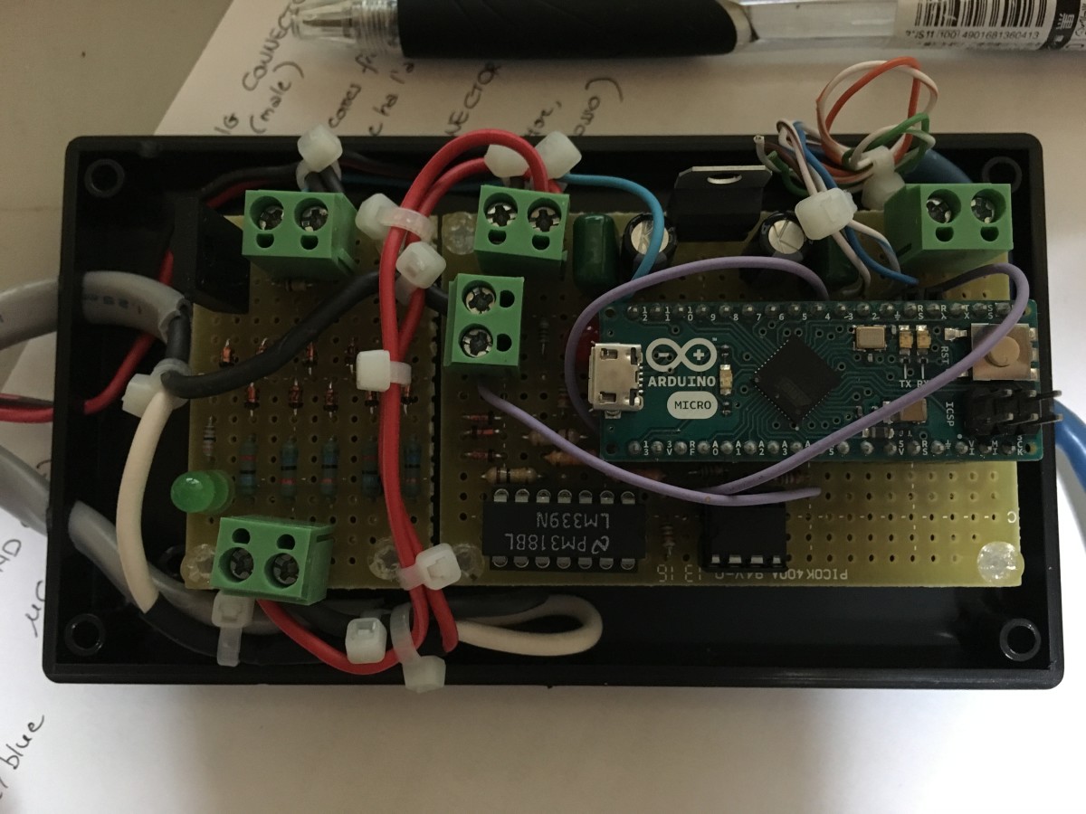
The layout of the Electronic Fuel Injection ECU is visible in the figure below. The PDF version of the layout is available here: 20160207_ECU_layout.pdf.
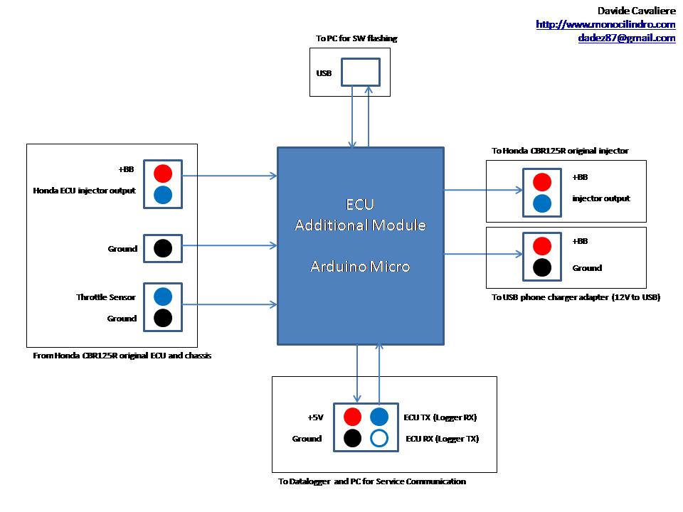
The ECU has many input and output plugs, which are needed to interface it to other systems around:
- Connector coming from the original Honda ECU injector pins (+BB and injector minus pin);
- Ground connector connected to the motorcycle chassis;
- Throttle position sensor (TPS) connector;
- Injector output connector (+BB and injector minus pin);
- Power supply for USB phone charger (12V to USB);
- Service cable (for Data Logger and PC data acquisition in real-time)
- USB cable (for software flashing of the Arduino Micro microcontroller).
The ECU electronic circuit schematics is visible in the following figure. The PDF file is available here: 20160207_ECU_schematics.pdf.
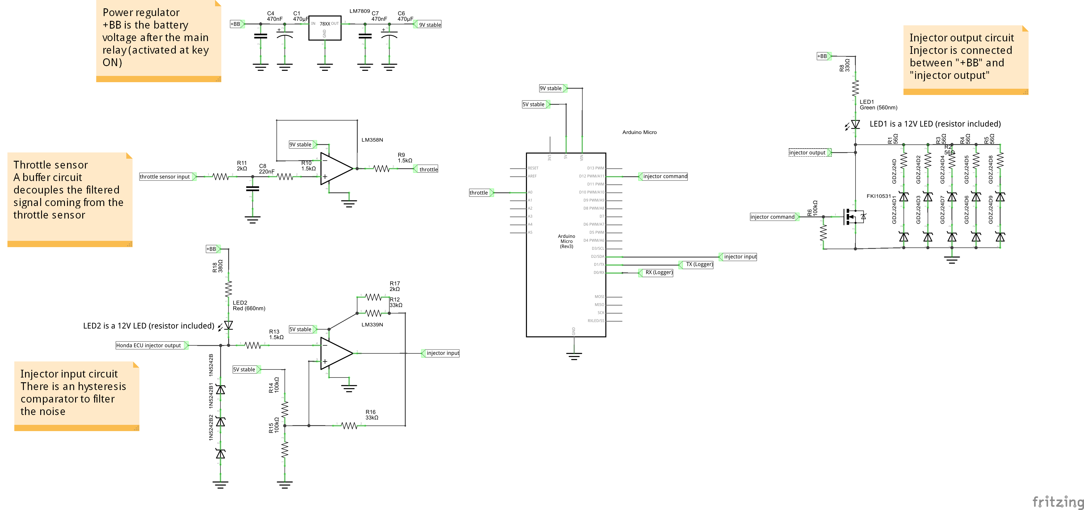
The schematics can be divided in the following areas:
- Voltage regulator. This circuit contains an LM7809 to convert the battery voltage (+BB, 12V nominal) to a 9V stabilized voltage. This voltage is used as a power supply for the Arduino Micro, and for the LM358N operational amplifier;
- Throttle Position Sensor (TPS) buffer circuit (operational amplifier LM358N). The TPS installed on the motorcycle provides a signal in the voltage range 0V-5V;
- Injector input signal circuit (from Honda original ECU). This signal has 2 statuses: 12V (injector open command) and 0V (injector close command). In order to filter any noise, an hysteresis comparator has been added, using an operational amplifier comparator (LM339N).
- Microcontroller Arduino Micro. One analog input (A1), one digital input with interrupt (pin 2) and one digital output (pin 12) have been used.
- Injector output signal circuit (to Honda injector). The signal coming from the Arduino Micro activates/inhibits the N-MOS Power Mosfet (FKI10531) and controls the status of the injector (open or close).
The following video shows how the DIY ECU operates. The red LED shows the signal coming from the original ECU (a signal generator, in this video). The green LED shows the signals output to the motorcycle injector (in this video, this signal is connected to the oscilloscope probe).
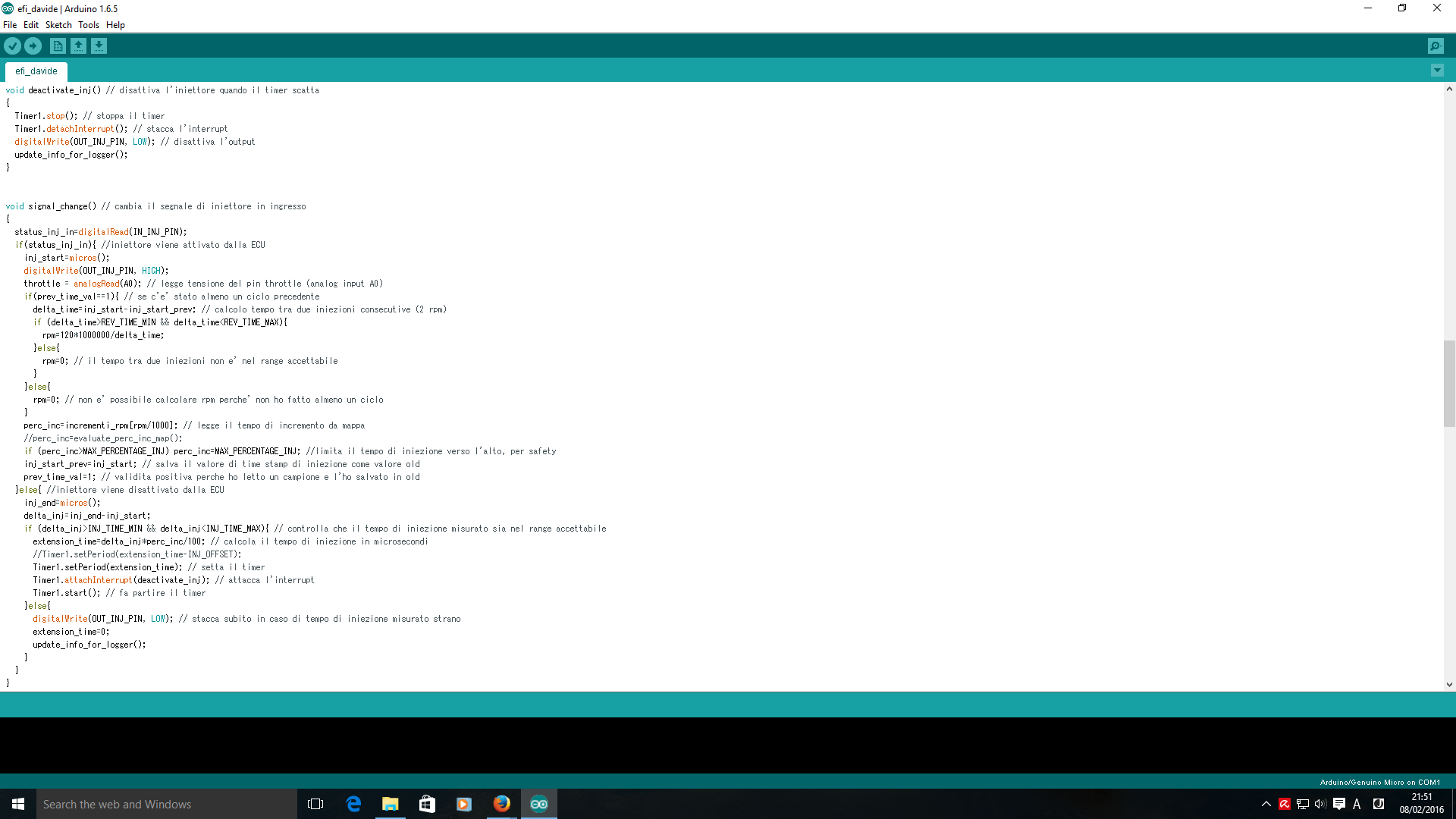
The SW logic has been programmed using Arduino IDE, and it is partially shown in the figure below. Details on the software structure are discussed in another article. Check it out.
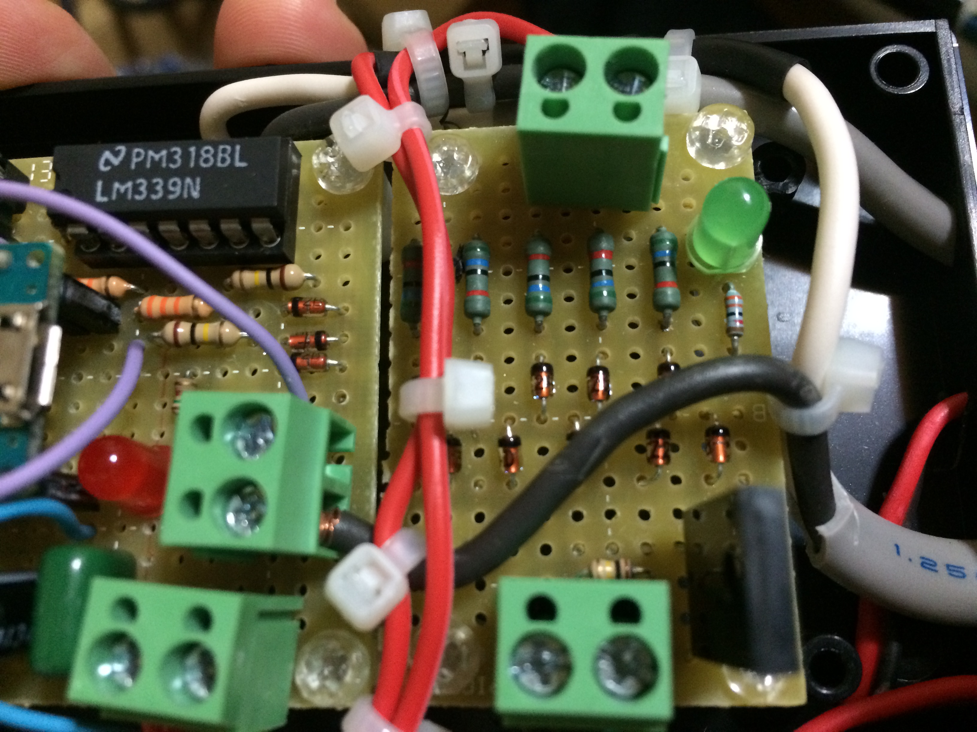
The figure below shows, on the right side, the injector control circuit. It is composed by a FKI10531 N-MOS Power Mosfet, and a network of Zener Diodes (GDZJ24D) and resistors with the purpose of limiting the injector voltage at the time when the transistor opens (injector closes).
Hi There
Interesting piggybag system you have there. Regardingh the schematic you posted, I were quorious about the Honda ECU injector output. I know it is a open drain system, but i do not see a pull up path other than the led + resistor. Have you had any problem in detecting the "off" side of the Honda ECU injector output signal. Also have you had any bad reading with the system?
A extra feature you could add for the extra input you have is a quickshift. Just a thought.
Heep it up.
Thank you for your comment.
You are right. There is a LED with series resistor, the positive pole is connected to 12V. When Keihin ECU Mosfet turns on, the current flows through the LED and the pin is 0V, otherwise it is 12V in open case. There is an Hysteresis comparator, LM339, with 3.3 V threshold. Up to now, no problem, it works perfectly. During cranking, the signal is a bit noisy, but I am working on an algorithm to filter the noise, it will be available in some days on beta3.
Hi, there're 9 signal inputs in one rotation , how to you solved it?
Hi david i'am from Indonesia
if on daily use does this arduino-based ecu survive? would not it be excessive heat?
I have run more than 5000km... No problem until now 🙂
Can u please send me the filesi can send out to be made please I've spent days weeks online tryna make this work and the files I do find don't work on any sites help please just want it run 1 injector 1 cylinder 212cc four stroke cdi 4pin unit I'm willing to purchase it made from uasap
Hello.
Well first thank you for this nice project !!
a question: this make a big diference if i use 15 picoF instead of 10PicoF capacitor ?
Even you speak about 2 pieces of 1 MicroF capacitors in the soldering and schematics, but in the BOM you speak about 1000 PicoF, but 1000 PicoF = 1 NanoF ..
Cheers.
Sorry, this is a mistake. For analog signal filtering, I suggest you to use a capacitor of some pico Farads. Too much capacitance will delay the signal (filter too strong). Too small capacitance will have no effect in filtering noise/spikes.
Thank you for the time and effort spent in developing this elegant solution and also for generously sharing your work. I'm not familiar with Arduino so I've ordered both a beginner's book and kit to learn enough hoping to build your ECU piggyback unit. I've wanted to port my CBR125R's cylinder head and install a high performance camshaft and exhaust system. What has been holding me back is the problem of metering the fuel injection system. My experience dates back to the era of carburetors when changing the jets would have provided the necessary improvement in fuel flow . Your DIY ECU unit is the solution. Once again ... thank you for sharing your work with the CBR125R community.
Thank you very much for your comment. I am happy that this project can be helpful to so many people.
Us, engineers, have to do our possible to help people to achieve knowledge. 😉
I agree with you, tuning the injection is not easy, you need to do it by trial-error, by checking the influence of your injection time to the lambda. You can do that by monitoring the signal from the lambda sensor, and increasing little by little the injection time (=injection quantity of gasoline). You should find an optimum value (which depends on the speed and throttle) that lets you achieve a mixture which should be slightly "fat" (more gasoline than air). In electronic terms, this means having a voltage on the lambda sensor of about 0.3V.
Dear Davide,
Can i use LM1949 for driving my injector ?
https://www.google.fr/url?sa=t&rct=j&q=&esrc=s&source=web&cd=1&cad=rja&uact=8&ved=0ahUKEwjOte7awv_YAhUBbxQKHWWkDkwQFggnMAA&url=http%3A%2F%2Fwww.ti.com%2Flit%2Fds%2Fsymlink%2Flm1949.pdf&usg=AOvVaw3hZ1iu0ysnZzCVlwuDGJUg
It is not enough. If you want to drive the injector, you need to use a power Mosfet or BJT, in order to control the current flowing in the injector. Basically, Fuelino provides an ON OFF signal, but this signal controls a MOSFET, which physically drives the current into the injector. I think that any MOSFET handling more than 2-3A and with a max withstandable reverse voltage > 60V should do the job. Also, make sure that the gate voltage of 5V is enough to turn it ON.
I want you to show me, how it connects to the wire in the motobike? . Namely 33 feet of wire in the motobike. Thanks bro.
https://www.monocilindro.com/wp-content/uploads/2017/01/IMG_3197.jpg
I want you to show me, how it connects to the wire in the motobike? . Namely 33 feet of wire in the motobike. Thanks bro.
hello david,
i have queistion, this ecu can use for drive / custom/ edit the signal to injector , or just for monitoring ?
thanks a lot
Hi Davide!
First of all, thank you for sharing with us.
In fact I was looking for a way to only read the information via the diagnostic connector of my HONDA XRE 300 and view it via cell phone with a TORQUE APP, for example.
Its design, however, makes it possible to correct a chronic defect of the XRE300. Due to environmental issues, HONDA BRAZIL has leaned to much the air-fuel mixture, which causes high temperature in the cylinder head and consequently cracks in the head. A question: How to connect the Arduino with the diagnostic connector ... elm327 or something like that would be necessary ...
Thank you
Ricardo
Buonasera e grazie per aver condiviso questo schemino basato su Arduino. Sarebbe interessante vedere una versione di ECU specifica per le turbine jet (uso modellistico). RPM, sensore di temperatura, ecc. Tutto con un display a colori (come la Xicoy) o un semplice lcd 16x2 … . Su internet si trova qualcosa ma non è garantita la resa e attualmente sto realizzandone uno e in attesa di finirlo per mancanza di componenti con sigle e valori vari. Grazie mille.