
Recently, for my IMU (Inertial Measurement Unit) project, I had the necessity to add low-pass filter, in order to reduce the noise on the accelerometer sensor signal. For this purpose, I decided to use a 1st order IIR (Infinite Impulse Response) filter, because it is easy to implement and run on a microcontroller.
In general, a IIR (Infinite Impulse Filter) is a numeric filter in which the value of the output depends not only on the values of the input, at sample time "n" and previous samples, but also on the status of the output at previous sampling times.
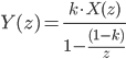
In case of a microcontroller, a simple IIR low pass filter can be implemented as below. The reason why this type of first order IIR filter is so widely used, is that it requires just an additional variable in RAM memory, to store the previous value of output signal, which is  .
.
The mathematical formula to be implemented for a first order IIR filter is as shown below.  is the filtered signal (output signal), while
  and are the input signal, and the output signal at previous sample, respectively.

In the above formula,  is the "filter constant".
- High "k" means a small filtering effect. The input signal is less filtered. The limit condition is
 . In such condition, only the input signal is used, and the output old signal does not have any effect.
 - Low "k" means high filtering effect. The input signal is filtered more and more depending on how you reduce "k". This is due to the fact that, reducing the value of "k", you reduce the influence of the input signal sampled at present time. This has a positive effect in noise filtering, but a negative effect, because it introduces a delay in the response. In other words, the step response becomes slower.
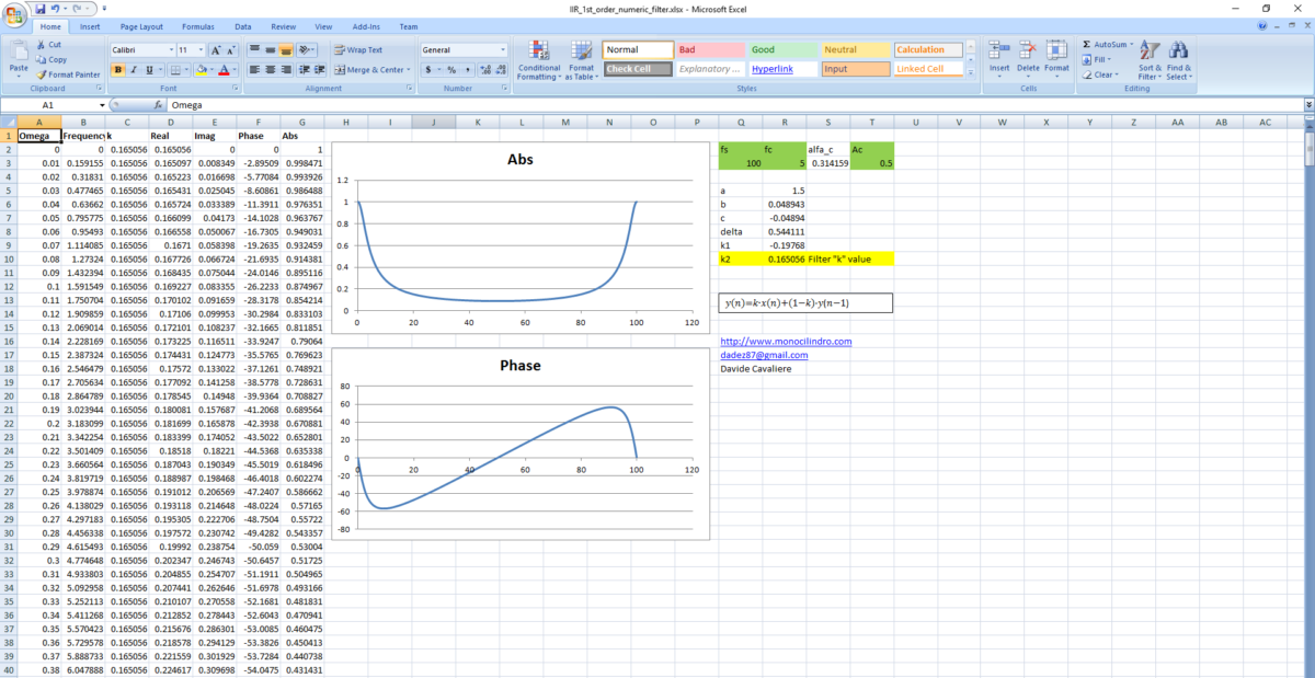
The frequency response of a first order IIR filter can be easily evaluated by calculating the Z-transform:

Which is the same as writing:
The Fourier Transform can be obtained by substituting:

After this step, it is possible to calculate the absolute value (attenuation of the filter) and the phase, depending on the frequency (omega) and filter constant "k".
I created a simple tool (download at the end of this page) which allows you to calculate the "k" filtering constant that you should use depending on the sampling time (sampling frequency) that you are using, and the attenuation that you want to get at a specific frequency, in Hz (cutoff frequency).
For example, in my IMU project, I am using a sampling frequency of 100Hz, and I want to have an attenuation of 0.5 at a frequency of 5Hz. As a result, the filter calculates a constant k=0.165056.
 Download:
ciao Davide ...
ieri ho realizzato il mio primo dsp grazie a queste righe a proposito del iir passa basso .il problema consisteva ad avere un riferimento quasi come corrente continua per un treno di 64 letture a 12 bits che mi serviva come riferimento ad un comparatore a finestra (64 riferimenti caricati in un array ), poi in parallelo a quello ne ho messo un altro con un inerzia piu' breve come valore da confrontare , insomma ho ottenuto cosi' una lettura di pixels abbastanza stabile provenienti da un sensore grid eye panasonic . la macchina è un arduino due che si comporta bbastanza bene ...work in progress... ciao isidoro