
This guide will show how to mount a complete Fuelino board. In order to mount, at home, the Fuelino Proto3, the following components are needed. A soldering station is required to solder the components.
For the complete list, please check the BOM (fuelino_proto3_bom). Schematics and board layout are available here: fuelino_p3_schematic and fuelino_p3_board.
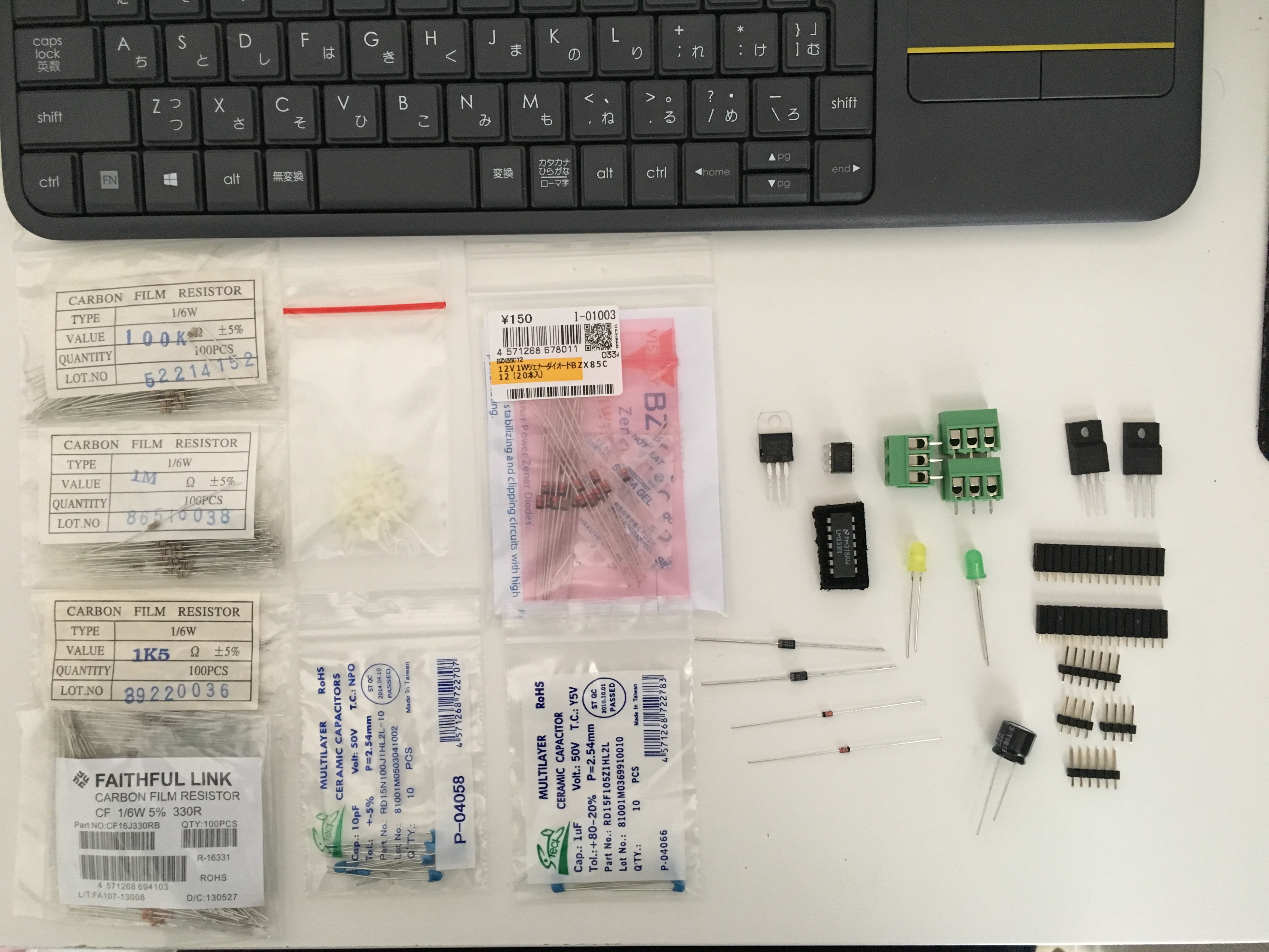 First of all, I mounted the resistors, in order: 3 pcs of 100kOhm, 2 pcs of 1MOhm, 1 pcs of 330 Ohm, 9 pcs of 1.5kOhm.
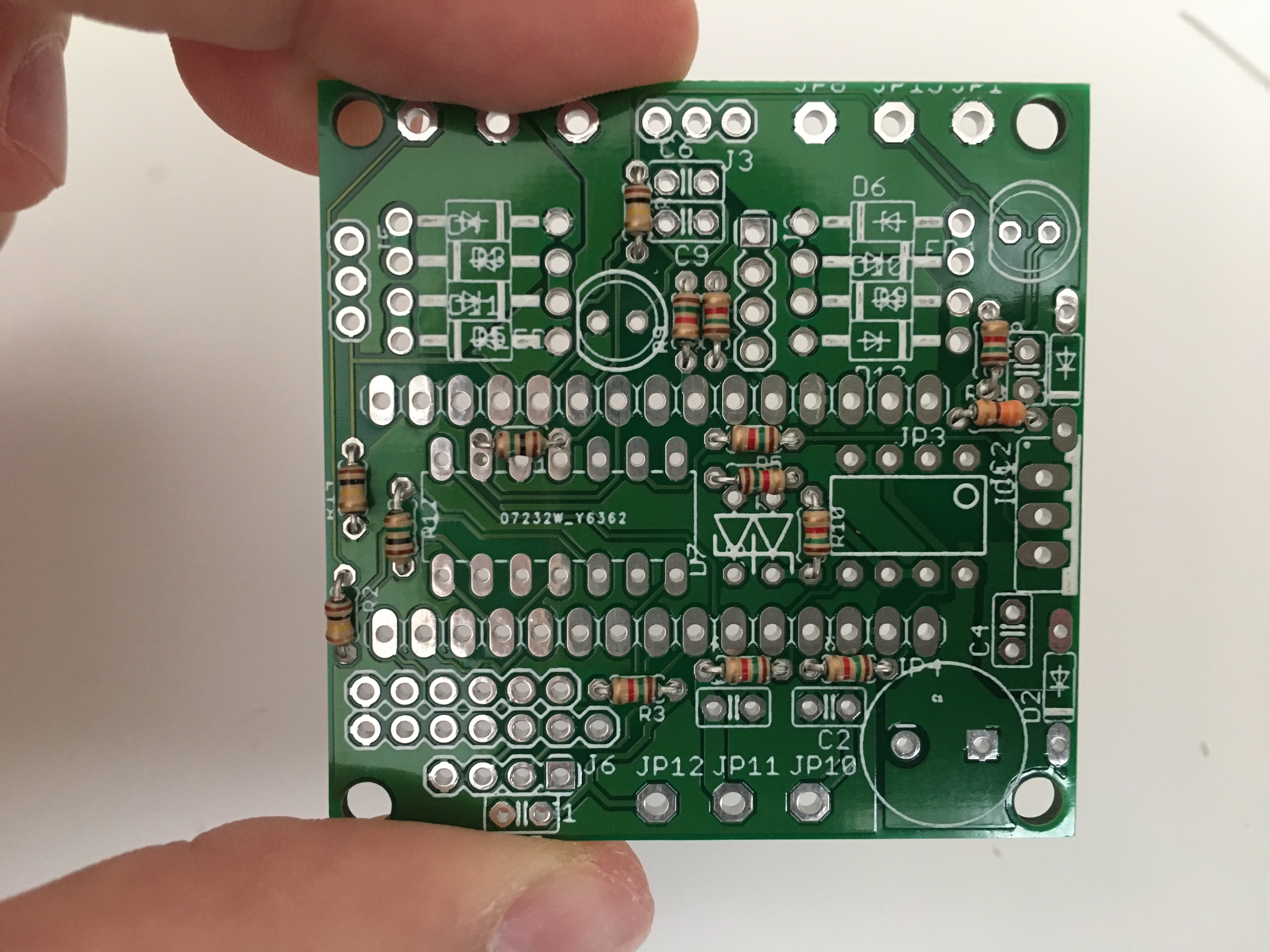 Then, I proceeded with the diodes: 2 pcs of 5.1V Zener diodes (1N5231), 2 pcs of standard diodes (1N4007), 8 pcs of 12V Zener diodes 1W (BZX85C).
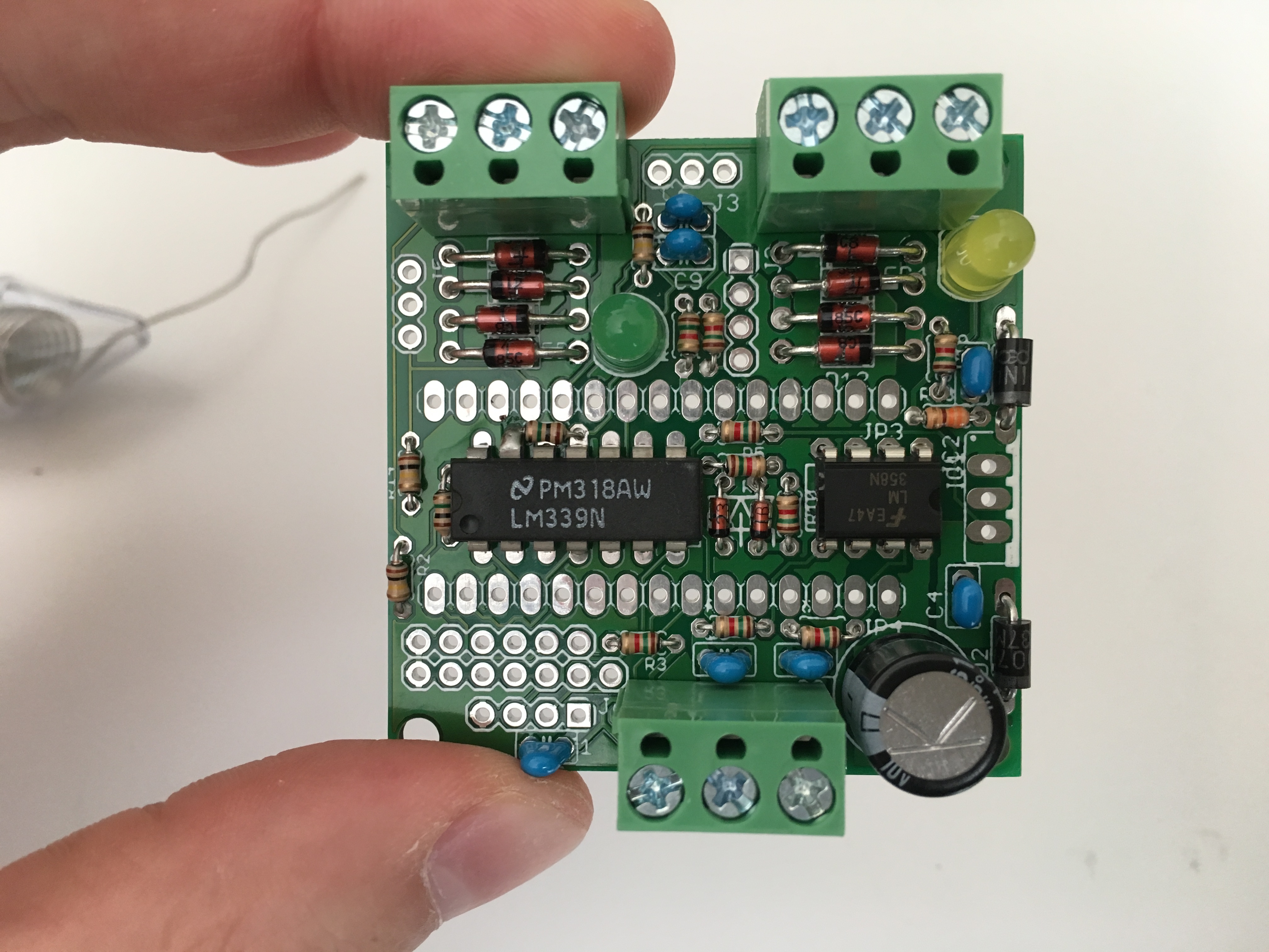
 Then, LM339N (comparator) and LM358N (buffer).
 The following steps was to mount the small capacitors, 2 pcs of 1uF, 5 pcs of 10pF.
 In the following step, I mounted 3 pcs of green connectors, and the LEDs. And also the big capacitor (it stabilizes the 9V power supply).
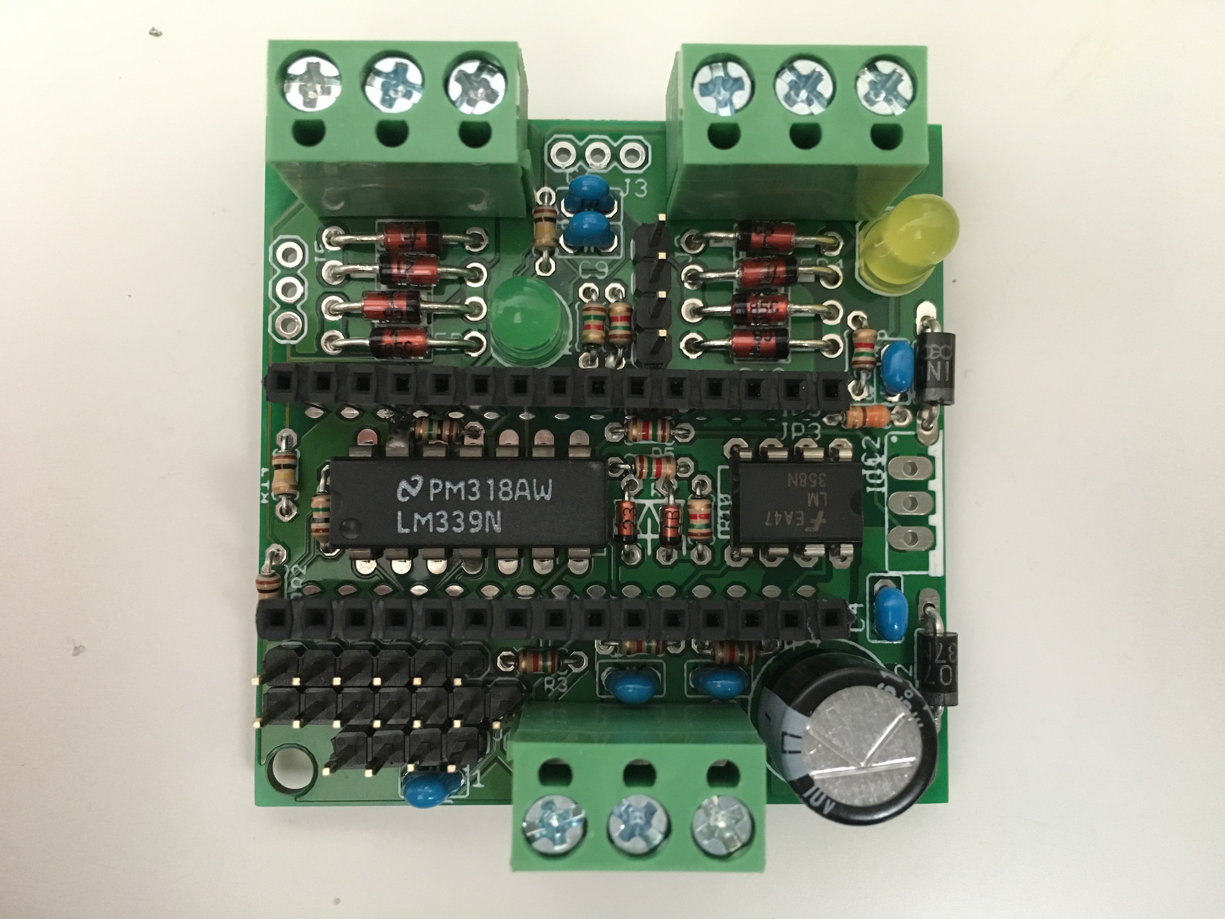
Then I mounted the connectors for Arduino Nano (15 pins + 15 pins), and also the other small connectors: one UART connector (4 pins), two SPI connectors (6 pins and 7 pins), and one I2C connector (4 pins).
 Finally, the last step was to mount the 9V regulator (L7809) and the two MOSFETs (FKI10531).
 Actually, the final step was to mount a 1.5kOhm resistor between 5V and A6 pins of the Arduino Nano (to be able to acquire when the battery voltage drops, after key OFF event). I also glued 4 spacers.
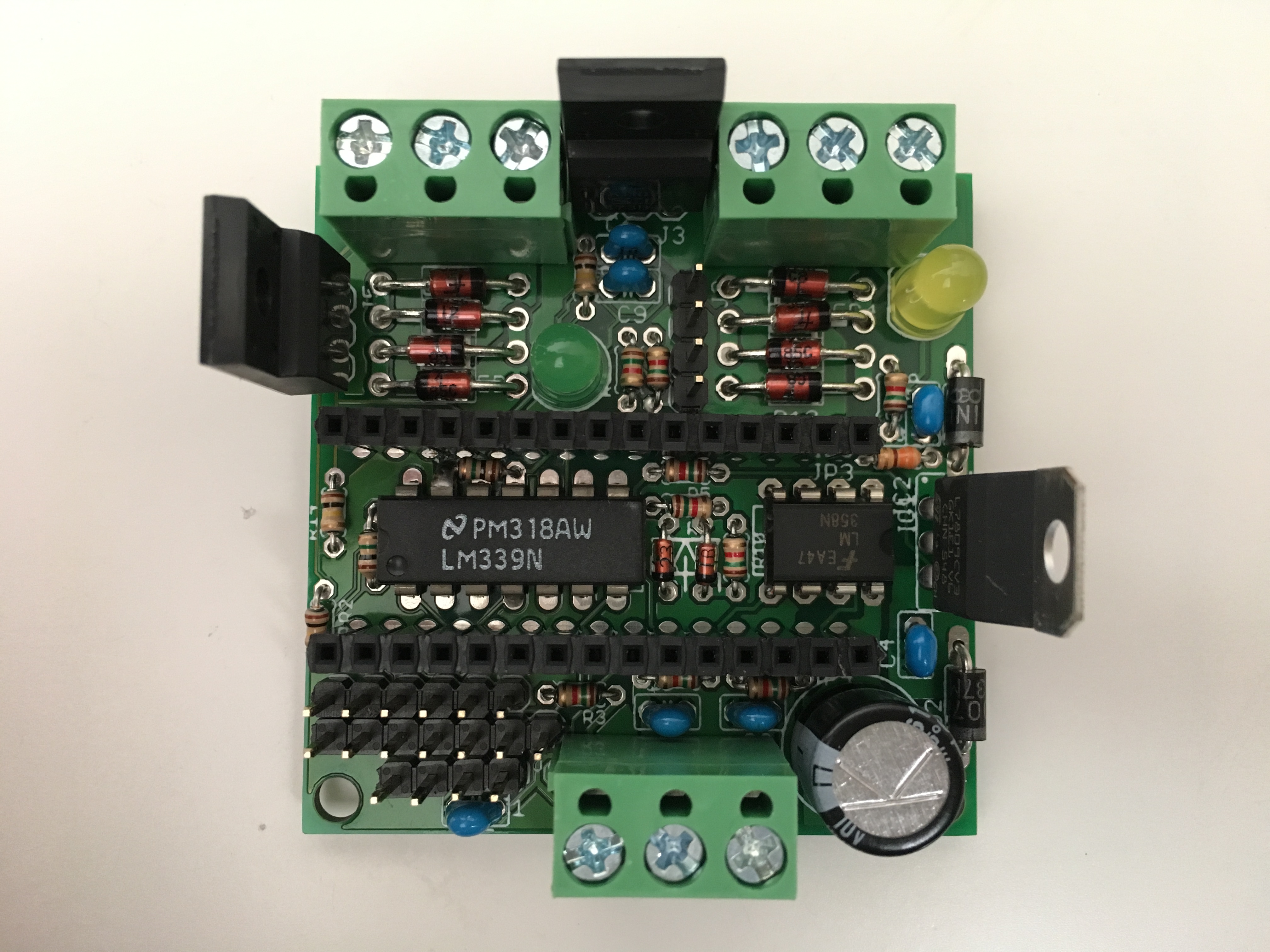
 Below, the complete board is shown, after mounting an Arduino Nano rev3 on it.
 The complete assembly process required about 45 minutes. I recommend to prepare all components in advance, in order to save time and avoid mistakes.
Hi David,
I'm very interested with this work.
Can you suggest me a replacement for Mosfet FKI10531, since i'm not familliar with electonic and i cant find that Mosfet in my local marketplace.
is IRF510/IRF520/IRF530/IRF540 compatible to replace FKI10531?
Thanks
Regards
Hello Fendy, I suggest that you print out the datasheet of FKI10531 and bring it to an electronic shop, they can help you. The important thing is that the shape is the same, I mean, the position of the pins should be the same (drain, gate, source) otherwise it will not work and you might break the board. Considering that the injector current is in the order of 1A or 2A, you should get a Mosfet which has low Rds(ON) when Vgate is 5V (coming from the microcontroller), so that you have a small drop at 1A. Last, remember that the Mosfet should be "N" type.
Can any one suggest me any alternating mosfet for FKI10531?
Can any one suggest me any alternating mosfet for FKI10531?
"Actually, the final step was to mount a 1.5kOhm resistor between 5V and A6 pins of the Arduino Nano (to be able to acquire when the battery voltage drops, after key OFF event). I also glued 4 spacers"
Hello davide. Sorry for bad my english,
If you turn your board facing up then the resistor will be on pins A0 and A2, not on A6 and 5v.
or maybe I was wrong