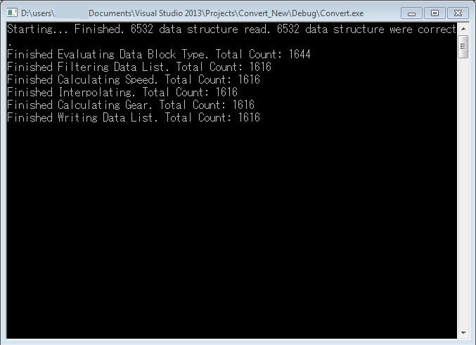
Here is an example which explains how to analyzed the data logged when riding the motorcycle. First of all, the raw binary data, which is saved on the SD card, must be converted into an easily manageable Excel file. This step is performed by a tool which I created using Microsoft Visual Studio Express 2013. The tool parses the binary file and interpolates the data.
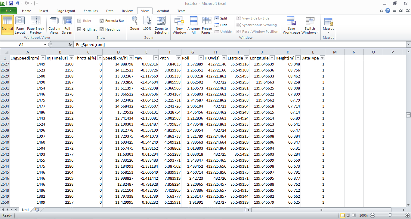
The output file is an Excel file which contains the following data columns:
- Engine Speed (rpm, rotations per minute), obtained from ECU
- Injection Time (us, microseconds), obtained from ECU
- Throttle position (%), obtained from ECU
- Speed (km/h), calculated by differentiating GPS latitude and longitude data
- Yaw angle (deg), calculated using Madgwick filter of Arduino 101 IMU
- Pitch angle (deg), calculated using Madgwick filter of Arduino 101 IMU
- Roll angle (deg), calculated using Madgwick filter of Arduino 101 IMU
- iTOW time (s), GPS week time
- Latitude (deg), obtained by GPS module
- Longitude (deg), obtained by GPS module
- Height (m), obtained by GPS module
ECU Data Type (1) and IMU data are logged 3 times per second, and GPS Data Type (3) is logged 1 time per second. The tool described above interpolates data, so that 4 rows are sampled each second.
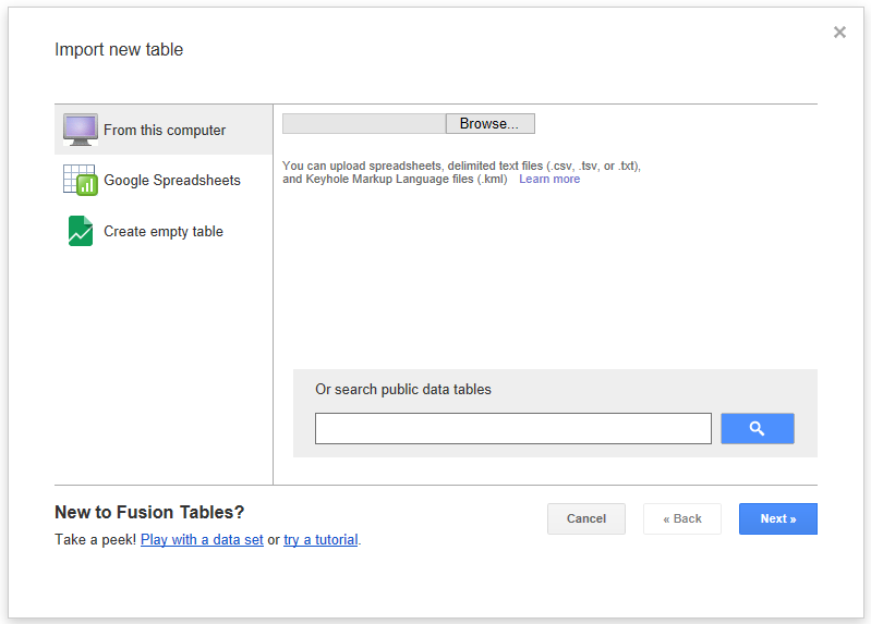
The Excel file obtained above is then imported using Google Fusion Tables functionality included in Google Drive. The import procedure is shown below.
At first, choose the file to be imported.
A preview is shown.
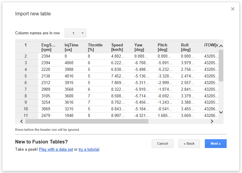
In case the column "Latitude" and "Longitude" are included in the Excel file, a new sheet named "Map of Latitude" will be automatically created.

The complete set of logged points is shown on the Google Maps image, allowing you to click on each point and visualize the value, for each signal, sampled on that point. In the example below, the following data are shown: engine speed (5047 rpm), fuel injection time (2694 microseconds), throttle position (13%), speed (62.31 km/h), roll angle (-3.154 deg), and so on.

Hello,
First, "bravissimo" as we said in Italian (I have learned some words when I was working for Yamaha near Monza). Your projects are awesome! You seem to be passionate by motorcycle and electronic§ I am also. Are you working in two wheeled vehicle field?
Currently I am PhD student and I am working on motorcycle active safety systems. To validate theorical results I am designing a data logger using "low cost" architecture. I am using an arduino mega associated with an IMU, two wheel speed sensors, a GPS and a steering sensor. I have some problem with loop speed. I am trying to save on a SD the IMU, GPS, WSS, Steering data at 100 Hz and the GPS at 20 Hz but it is not easy. I have seen that your project is based on the following refresh times: 3 times each second for the whole of sensors expect the GPS which sample one time per second. Do you think it is possible to start from your sketch and increase the sample rate to reach 100 Hz?
Thank you very much,
Pierre-Marie
Hello, and thank you for your comment. Your project seems interesting.
I think that one of the biggest problems is the SD card speed. The latency is very high, and it might take 200ms or so to write one data block.
For this reason, the sensor data reading should be processed using interrupts, while the SD card writing should be in an other "task", for example in the main loop, and you should use a buffer.
My project was very simple, I think it is hard to reach such speed that you want to achieve, using my code.
By the way, how much data (bytes) are your sensor creating, for each "read"? They should put their data in a buffer, and then on an other task you go to read that buffer and check if someone wanted to write on the SD, and then process the writings asynchronously.
Basically, buffer filling, and reading, should be asynchronous. Is it clear?
Hello,
You are right write data on the SD consumes sometimes long time leading inevitably to timing problem for such sample rates.
I asked my first question because I wanted to know the max recording speed reachable with your code without any modification.
If you are interested about the topic, with the assistance of a moderator on the arduino forum, we have worked on a motorcycle datalogger able to record:
- steering angle (100Hz)
- IMU data (x9) (100Hz)
- wheel speed (front & rear) (100Hz)
- GPS (20Hz)
It almost works:
https://forum.arduino.cc/index.php?topic=438840.0
I am very interesting about your code to acquire ECU data. One time again awesome job!
Where did you find the way to decrypt the messages?
I have a KTM so for sure the communication messages are very different from the Honda.
Thank you very much,
Pm
I saw your post on the Arduino forum, and that is pretty interesting. I also saw the code, and thank you so much! First of all, I didn't know about the library "SDFat". I tested it and it it pretty fast, compared to the standard "SD" included in Arduino IDE. I am now using it for my project Fuelino. And also, I did not know about the existence of a "yield" function: this is very good news, since now I understood that I can get data from IMU while the SD card is busy writing data. I will use circular buffers. In my application, the IMU is a cheap MPU6050, which produces 12 bytes per "sampling", since each axis data (3 accelerometer + 3 gyroscope) is using 2 bytes (16 bit integer). I think I will be satisfied with 20Hz, or 50Hz maximum. The idea is to log raw data using Fuelino, and then the PC "offline" will convert the raw data into yaw, pitch, roll, because that requires floating point operations, and ATmega328p (Arduino Nano) does not support them.