In this article, I will show you how to connect a LCD display to Arduino 101. In my case, the display is an AQM0802A-RN-GBW (I2C接続小型キャラクタLCDモジュール 8x2行), which I bought at Akizukidenshi, in Akihabara, for 600 Yen (4 Euro). The display controller is Sitronix ST7032 (datasheet can be downloaded here: Sitronix ST7032 Datasheet), and the display has 2 lines of 8 characters.
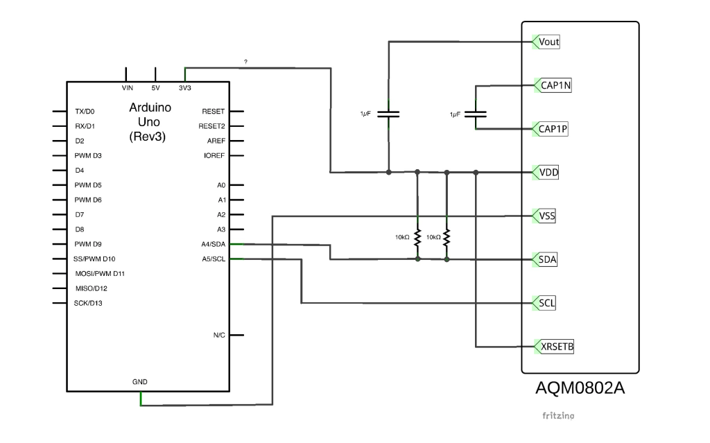
I2C communication protocol is used to tranfer data between Arduino 101 and the display. Technical details of the protocol can be found on Wikipedia. The I2C communication protocol was invented by Philips in 1982, and it is a master-slave communication protocol. In this case, since the communication direction is only from master (Arduino 101) to slave (Sitronix ST7032), only 4 wires have to be connected. In addition, XRSETB can be optionally connected.
- VDD: 3.3V (Power supply)
- VSS: 0V (Ground)
- SDA: Arduino 101 pin A4 (Master data)
- SCL: Arduino 101 pin A5 (Master clock)

SDA and SCL pins are used to transfer data between Arduino 101 and the display. Since these are digital signals, the status can be only 0 or 1. According to I2C protocol standard, the bit is forced to logical state 0 by closing the circuit to ground (0V), and set to logical state 1 by leaving the circuit open (3.3V).
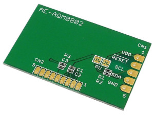
In my case, it was not necessary to add any resistor or capacitor, because they were already present on the PCB.

In order to communicate using I2C protocol, it is necessary to include the Wire library ("wire.h"). The display I2C slave address is 0x07. Also, this display uses a particular communication protocol to transfer data, which consists of transfering 2 bytes at once (each "Instruction Code" is composed by 1 byte for for control, plus 1 byte for data). The details are well explained in the datasheet, but I also found a Japanese website which easily explained how the protocol works.
Also, thanks to the guy who made it, in Internet I found a library (download: arduino_ST7032-master) which can be included in the Arduino project to easily manage the display commuication. Inside the ZIP file, there are also some examples which show how to use the library. By setting the content of each DDRAM memory address, it is possible to visualize each of the following characters. By setting the CGRAM, it is also possible to program additional customized characters.
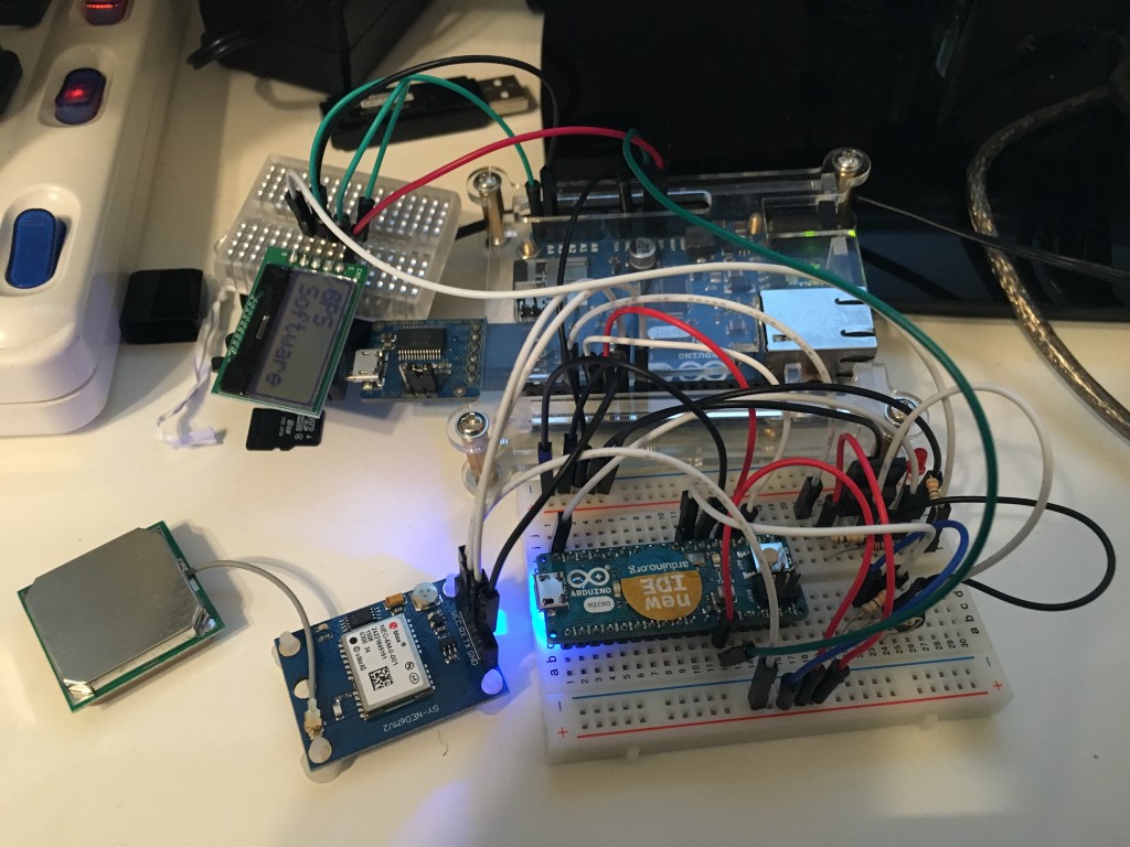
Finally, the result. In the following picture, the display is connected to an Arduino Ethernet board. However, the result is the same on an Arduino 101 (pinout and libraries are compatible). There are many cables which are not needed, in the following picture (you only need to connect 3.3V, GND, SDA/A4 and SCL/A5).

The code to be compiled is very simple:
|
1 2 3 4 5 6 7 8 9 10 11 12 13 14 15 16 17 18 19 20 21 22 |
// include the library code: #include <Wire.h> #include <ST7032.h> // initialize the library ST7032 lcd; void setup() { // set up the LCD's number of columns and rows: lcd.begin(8, 2); lcd.setContrast(30); // Print a message to the LCD. lcd.print("hello!"); } void loop() { // set the cursor to column 0, line 1 // (note: line 1 is the second row, since counting begins with 0): lcd.setCursor(0, 1); // print the number of seconds since reset: lcd.print(millis()/1000); } |


Hi Davide!
Thanks for the nice instruction page!
My goal is to combine the display with a combined BME280 PHT sensor on the i2c bus.
Display needs to show:
1013hPa
60% 25.5C
Looks like it is just going to fit.
Thanks to your easy instructions it was quite simple to get a 16x2 LCD running.
The AQM1602Y-RN-GBW is available for ¥450 at Akizukidenshi.
It comes with the two 1uF capacitors. One for Vout to Vdd and one to connect to CAP1N and CAP1P
Instead of the 2x 10k resistors, pull-up SDA to Vdd with a 4k7 resistor.
Did not follow Akizukidenshi's instruction sheet. Your example is easier with less components.
The display consumes about 0.45mA.
This works excellent chained together with a BME280 sensor over the I2C bus.
This clearly shows the advantage of Arduino I2C implementation for hooking up sensors and other peripherals like LCD 🙂
Hello, is the diagram OK? Do they have two 10K resistors on the SDA pin?
I think one 10K resistor has to go to SDA pin and one 10K resistor on SCL pin.
Thanks Mark