
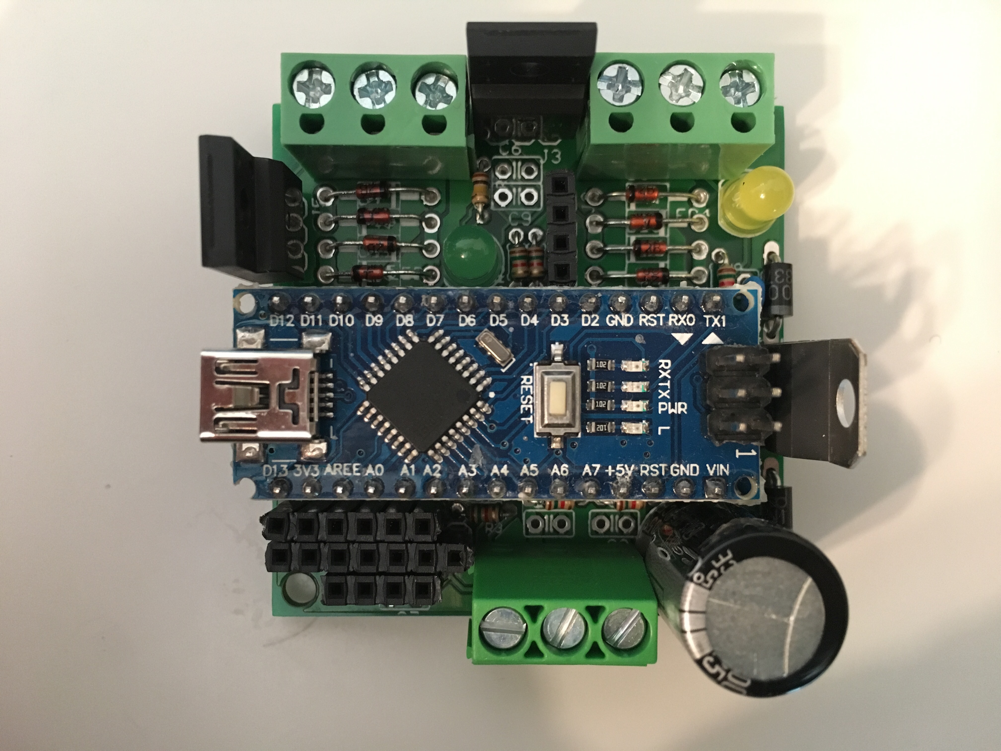
This morning, before going to work, I finally had some time to assemble the first Fuelino Proto3 board. Since this board is only for testing purpose, in order to save some time I did not mount filter capacitors, I mounted a cheap electrolytic capacitor that I had quickly available, and put some cheap 12V Zener diodes (500mW) since I still have to receive the 1W ones (they will arrive today from Akizukidenshi, hopefully). I am very happy because the components fit very well, without any space overlapping (not like Fuelino Proto2).
 However, I found out that in the electrical design, I made some small mistakes (damn it), which fortunately do not have a big impact on the functionality. I wrongly decided to use the pins A6 and A7 of the Arduino Nano (Atmel ATmega328p), erroneously thinking that they could be used also as digital input/output, with pull-up features. I was wrong. These pins only have analog digital conversion functionality.
Unfortunately, as shown in the schematics (fuelino_p3_schematic) and in the board layout (fuelino_p3_board):
- On A6, I connected the Enable/Interrupt pin (not the Slave Select pin, fortunately!) for the second SPI port, which corresponds to the 7th pin, from left, on the SPI port on the low left side of the board. In case this pin is not used, there is no impact on functionality.
- On A7, I connected the "battery voltage" reading. It corresponds to the output of a comparator (LM339) which changes status depending on the battery input voltage, so that the microcontroller can understand when IG switch (ignition key) is turned OFF by the driver. I wanted to use this info in order to stop SD memory writing in case battery voltage drops. Unfortunately, since A7 input does not have pull-up function, it is not possible to read the status, but I think that the problem can be bypassed by connecting an external resistor (1.5kOhm, in the picture below) between 5V pin supply and A7. In case this info is not necessary, there is no need to perform this modification (soldering on the back side).
 The next step will be to test the board and the software "on the desk" (with the Pico DrDaq signals simulation and acquisition environment). Once the board is working properly on the desk, I will test it on my motorcycle.
Can u help me in getting a nonefi kit or the build u made for my zongshen 190cc single cylinder 4stroke it has a 5 pin cdi ,6 pole stator 3phase ,28mm intake opening bolt holes measure out to 58 mm not 48 like normally or a parts list of everything electrical components to build the arduino 2560 to make one for it please I'll buy it if u can make it for me
Can u please give me a list of everything piece of board and components needed please I wanna install efi on my Honda grom swapped zs212cc motor