
This article shows how I am performing one part of Fuelino software validation. First of all, why is software validation necessary? The main reason is to verify that no software bug is present, and the second one is to make sure that the software behavior, in term of injection management, is according to the theory.
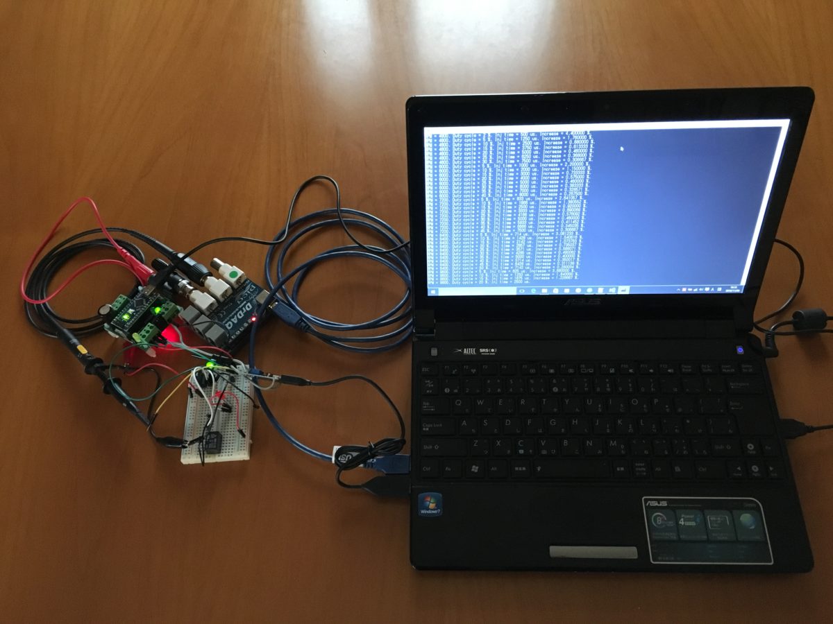
In order to make sure that the injector command timing (pulse width) is according to the percentage increment defined by the calibration maps, I developed an automatic tool for Pico DrDaq. The tool, which is visible in the picture below, has been programmed using Microsoft Visual Studio Express 2013 for Windows Desktop, in C++ programming language. The program communicates with the Pico DrDaq (oscilloscope and signal generator device) using the official library downloaded from Pico Technology website. The official PDF guide is available here: usbdrdaqpg-en-4. And the source code (Visual Studio project file) is available here: validation_test_20161105m.
 The tool is very simple: the DrDaq signal generator simulates the original ECU injection command signal (Fuelino input). The period of the simulation signal varies, in order to simulate many possible engine rotation speeds (RPM), and also the duty cycle, which corresponds to the fuel injector command pulse width, varies, in order to simulate the complete range of injector commands (from 500 microseconds to 7500 microseconds). The RPM range is from 1200 rpm to 12000 rpm, with 1200 rpm steps. While the signal is fed to the Fuelino, its injector output signal is also measured by the DrDaq oscilloscope channel, using the trigger feature. Once this signal is acquired, it is possible to calculate the pulse width actuated by Fuelino, to the fuel injector, and therefore determine if the pulse width percentage increase is according to the specifications (defined by the calibration maps).
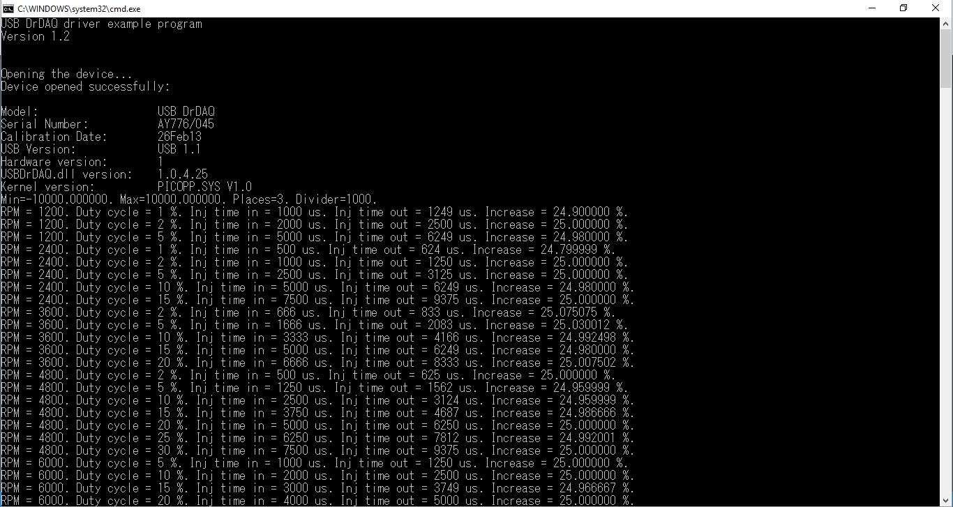 As shown in the screen-shot above, the tool shows in real time the results of the measurements. After the complete procedure (which requires some minutes, depending on the number of tests to be done), an Excel file in CSV format is exported by the tool, and can be imported in Excel (or other tools, such as Matlab), for post-processing: export_128increment_calcul_offset67.
 During this test, I wanted to make sure that, after setting the calibration map array elements "incrementi_rpm[]=128" (which corresponds to a fuel injection time increment of 25%), the injector command pulse actuated by Fuelino was exactly the desired value. As shown in the Excel graph in the picture above, the percentage of increment was close to 25% on most of the input injection pulse width, and RPM conditions (X axis). Sometimes there is a small error (0.1%) which is caused by actuation and measurements accuracy.
At present, this validation tool is able to simulate different engine rotation speeds (RPM) and fuel injector command pulse width times (microseconds). Therefore, the degrees of freedom are 2. In the future, I am planning to add an additional degree of freedom, which is throttle position sensor signal (0V - 5V range).