I will give you an advice about gyroscope data range when using Arduino 101 board. As you may know, this board integrates a Bosch BMI160 acceleration and gyroscope sensors unit. Datasheet: BST-BMI160-DS000-07.
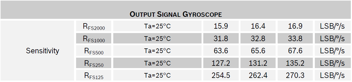
According to the datasheet, it is possible to choose between multiple data ranges. The default data range is 250 deg/s. Considering that the raw data is provided as an integer in 2 bytes format (maximum value: 32768), 1 deg/s of rotation speed will return a numeric value of about 131.2.
 However, when using the standard range (250 deg), I noticed that sometimes, when I rotated the board quickly, the gyroscope speed was saturating, and gave overflow problems. I give you an example below.
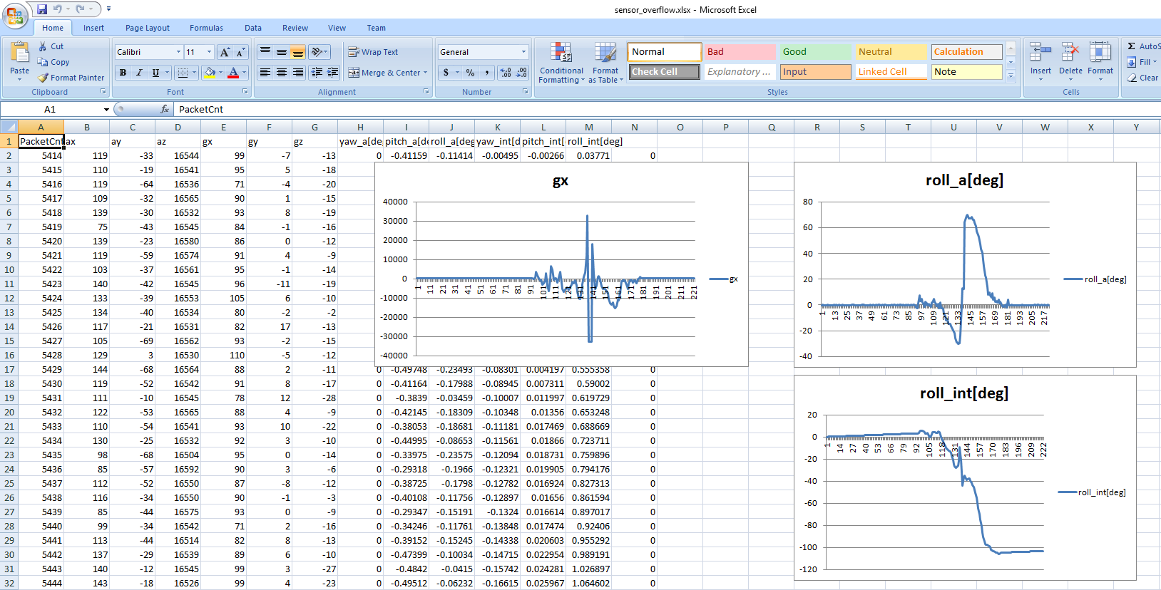 There are 3 graphs in the Excel file above (download here: sensor_overflow).
- "gx" is the raw sensor data received from Arduino 101, using Microsoft Visual Studio Express 2013.
- "roll_a[deg]" is the roll angle calculated using only acceleration sensor data.
- "roll_int[deg]" is the roll angle calculate using only gyroscope sensor data.
In the experiment above, I just moved quickly the board in clockwise direction, by hand. Before moving clockwise (positive angle), the hand at first makes a counter-clockwise movement, in order to charge the board with enough speed before rotating clockwise. As you can see in the graphs, the roll angle calculated using acceleration sensors data is correct. However, the angle calculated using gyroscope sensors data is wrong. The reason of this problem is caused by gyroscope signal saturation, as shown in "gx" signal waveform; the speed increases and, when crossing the maximum limit, the data overflows and this causes to think that the board is rotating in opposite direction. For this reason, angle increasing rate becomes opposite. Finally, when the speed reduces, the situation becomes normal again. However, angle computed using gyroscope sensors signals integration has an offset error.
In order to solve this issue, I tried to increase the gyroscope sensor range to 500 or 1000 using the Arduino 101 library function "CurieIMU.setGyroRange(500)" and "CurieIMU.setGyroRange(1000)". However, due to some mistakes in the official CurieIMU library, the change was not applied correctly, and the gyroscope continued to use the standard gyroscope range (250). At the moment, I am using Arduino IDE 1.6.9, and the Arduino 101 package (Intel Curie) version installed is 1.0.6.
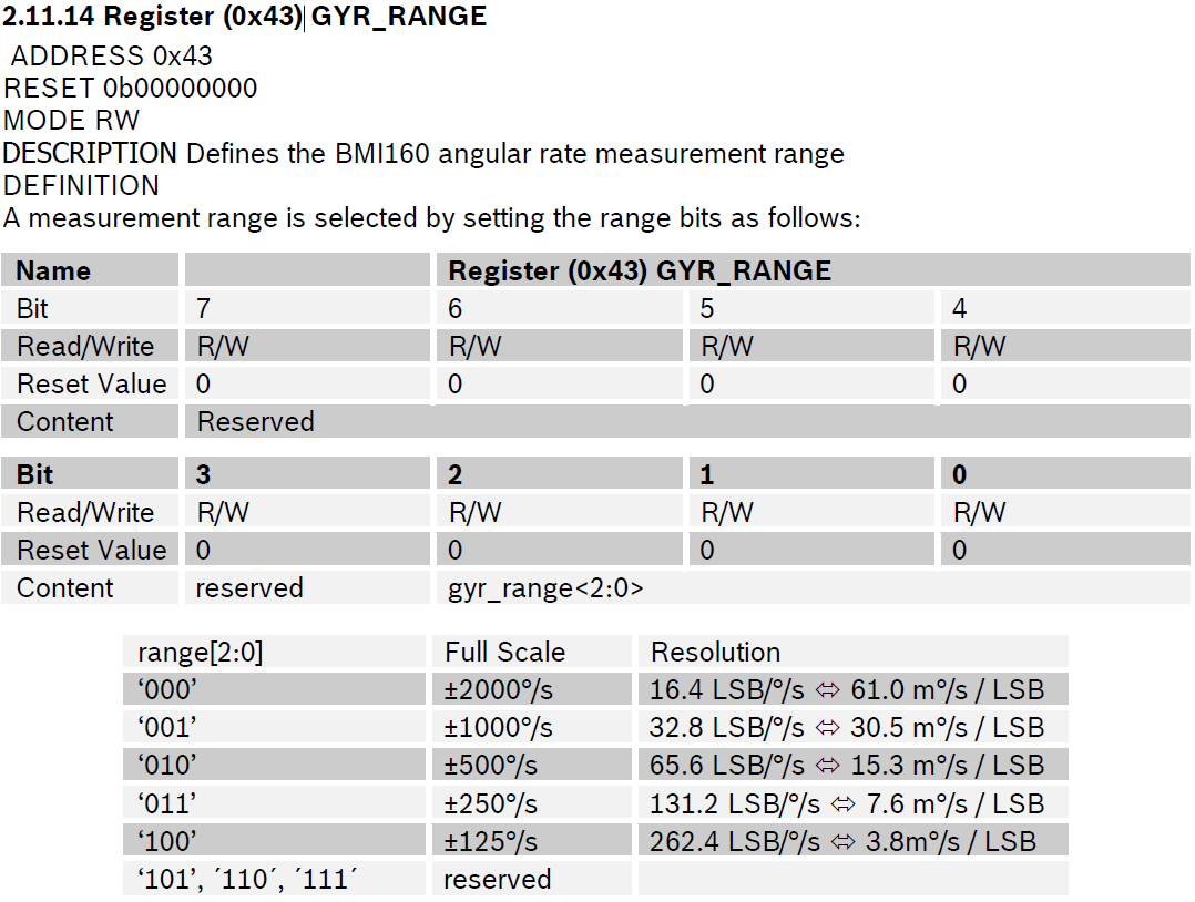
In order to effectively set the gyroscope range to the value that I wanted (1000 deg/s), I needed to brutally implement the change directly in the library. First of all, the library is located in the following folder: "C:\Users\%your_user_name%\AppData\Local\Arduino15\packages\Intel\hardware\arc32\1.0.6\libraries\CurieIMU\src". I opened the file "BMI160.cpp" and find the function "BMI160Class::initialize()". In this function, I modified the "setFullScaleGyroRange(BMI160_GYRO_RANGE_250);" to "setFullScaleGyroRange(BMI160_GYRO_RANGE_1000);". After compiling Arduino sketch again, the range was correct (1000 deg/s). By checking deeply in the library code, I noticed that "setFullScaleGyroRange()" function is operating on memory address 0x43.
|
1 |
#define BMI160_RA_GYRO_RANGE 0X43 |
I will send an e-mail to the developers so that they can solve this issue. For the time being, please notice that a range change can be done only by modifying the library.
How could i convert IMU sensors data into Yaw Pitch and Roll.