
As you've probably already read in other posts, I created by myself an additional DIY ECU module, which I use to interface the original Honda ECU to the fuel injector. The reason why I added an ECU to regulate the injection timings is that I installed a bore up kit (166cc), which is requiring more air, and so more fuel is needed in order to maintain the proper stoichiometric air-fuel mass ratio. For this purpose I used an Arduino Micro microcontroller, which is reasonably cheap (around 3000 Yen, 23 Euro) plus some additional electronic components. The ECU is located under the passenger's seat, as you can see below. The open connector below, is the one which connects the additional DIY ECU to the fuel injector.

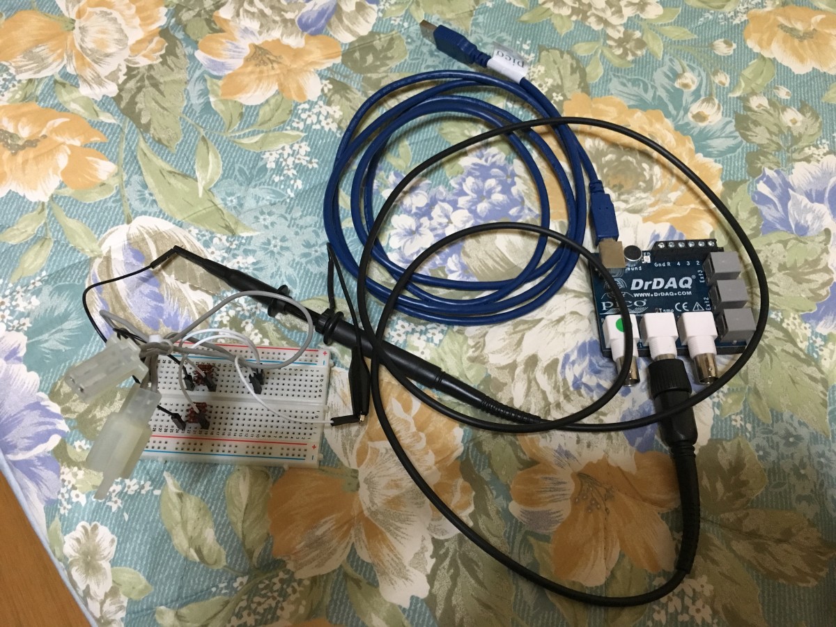
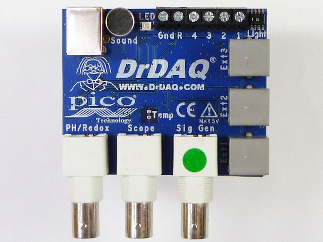
Today, I will show how you can measure the voltage and current flowing in your motorcycle's injector. This procedure is valid not only for a Honda CBR125R; it is a general procedure which you can apply to mostly every motorcycle injector. First of all, you need an oscilloscope: I used a Pico DrDaq oscilloscope, which I bought at Akizukidenshi, in Akihabara (Tokyo, Japan), for just 12,800 Yen (90 Euro). This oscilloscope has only 1 generator channel, plus 1 voltage measurement channel, and some other inputs/outputs that I have never used. Since there is only 1 measurement channel, I had to measure current and voltage separately.
First of all, let's see how the injector driving circuit of the ECU looks like. The injector is controlled ON/OFF by using the pin 12 of the Arduino Micro. It might seem stupid to say this, but I want to clarify: it is not possible to power the injector by directly using the digital output of the Arduino: first of all, the injector has a resistance of just 8-12Ω, which means that, assuming a nominal voltage of 12V, the injector electric current absorption is about 1A (Ampere); Arduino max current for each pin is just 20mA, which makes it barely capable of controlling a small relay. And also, an Arduino Micro outputs a 5V voltage, while the injector needs to work with battery voltage (nominal 12V). For this reason, the Arduino pin 12 signal is connected to an N-channel power MOSFET and to a pull-down resistor (100kΩ). As a power MOSFET, I decided to use a FKI10531, since it accepts high drain-to-source maximum voltages (up to 100V): considering that when the injector opens, the drain-to-source voltage can be also 60-70V, having a high maximum voltage was mandatory. And also, it can accept a maximum forward current of 18A (much higher than 1A required in this application), and the forward resistance Rds(ON) was reasonably low (54.5 mΩ max.). The datasheet can be download here: FKI10531.

In order to limit the voltage and discharge the energy accumulated in the inductance, at the time of injector opening, I used a network of resistors (56Ω) and Zener diodes (24V). Probably, using so many resistors (5) and Zener diodes (10) is not necessary, but I decided to over-size the circuit in order to avoid to destroy Zener diodes, due to overheating. In fact, the Zener diode (GDZJ24D) that I am using has a Zener voltage of 24V, and can dissipate only 500mW of power. Supposing only one Zener diode, and no series resistance, and considering an injector current of about 1A, when the injector opens, the Zener diode would have to dissipate, for a limited time (let's say, few hundreds of microseconds) a total power of 24W (24V and 1A); considering that, at 12000rpm (max engine speed, worst case), each injection happens every 10ms (12000 rpm means 200 rotations per second, which are 100 combustion cycles considering a 4-stroke engine), a discharging time of, for example, 300us, would mean a 3% duty cycle with 24W peak power (this means an average dissipated power of 0.74W): this power would break the Zener diode for sure. So, due to my incomplete knowledge of the injector inductance and real discharging time, I decided to take a "safe margin" and this is the reason why I decided to split the discharging power between 10 Zener diodes (5 lines, with 2 Zener diodes and 1 resistor each). The datasheet of the Zener diode can be found here: GDZJ24D datasheet.
First of all, I measured the injector voltage by connecting the reference pin of the oscilloscope (GND) to the motorcycle chassis, and the signal pin to the injector (-) pin, which also corresponds to the drain pin of the power MOSFET. The maximum input voltage of the oscilloscope is just 10V, so I had to reduce the signal amplification by setting the probe attenuation to "x10". The signal which I measured during engine cold idling, is as following.
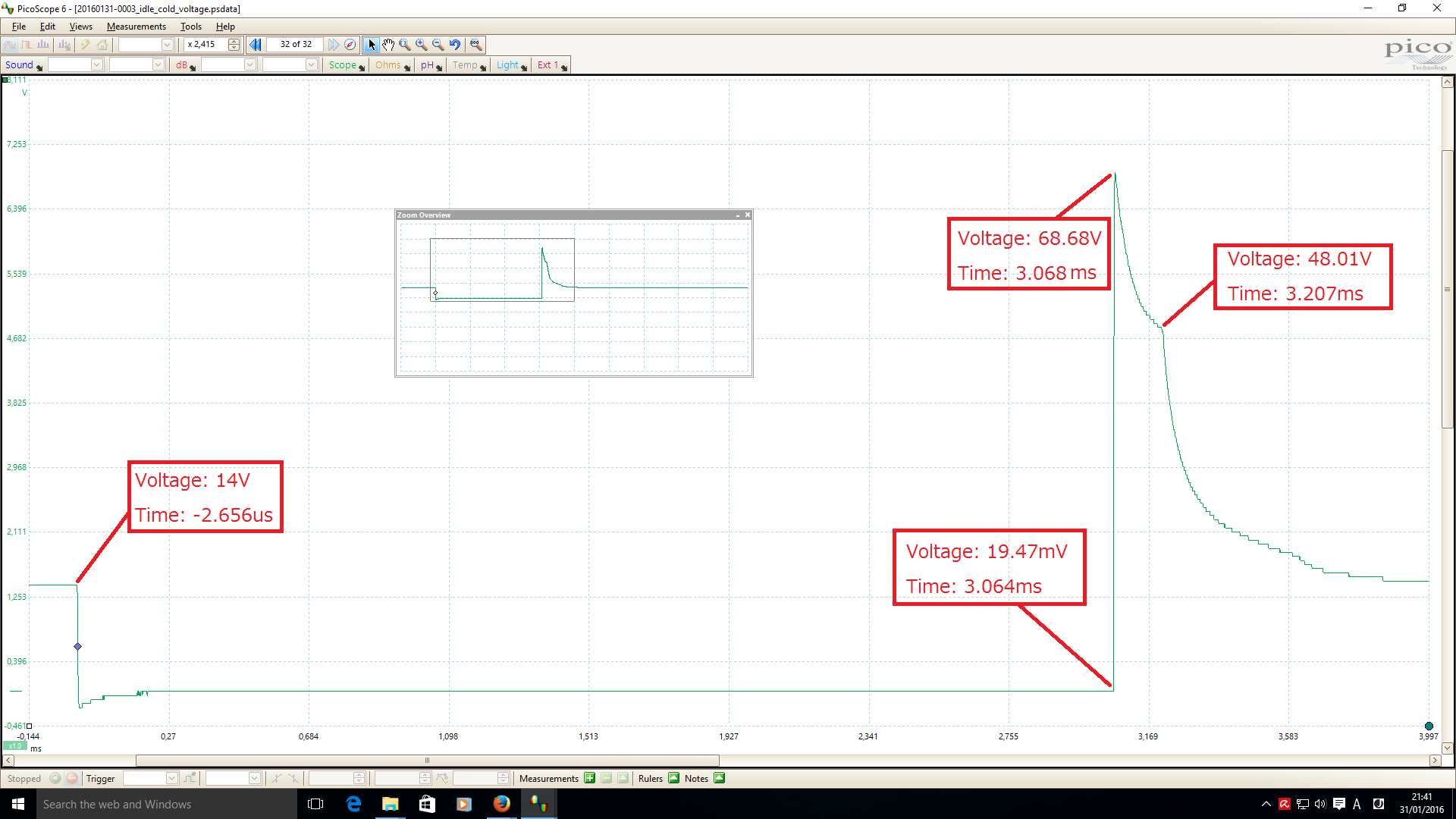
Injection phases can be resumed as following:
- Pre-injection: Arduino pin 12 signal is OFF (0V), MOSFET is open, and the injector (-) pin voltage is the same as +BB voltage (13-14V during idling). During this phase, the injector is closed and the fuel cannot flow through the injector;
- Injection start: Arduino pin 12 signal is ON (5V), MOSFET is closed, and the injector (-) pin voltage is about 0V (19.37mV in the screenshot) but not exactly 0V, since the power MOSFET has its own Rds(ON), and when an electric current flows into it, there is always a small voltage drop. In this phase, the injector current starts to rise up to its maximum value, which depends on the battery voltage and injector resistance, according to the Ohm's law
 . During the measure, I measured an injector current of 1.2152A;
 - Injection end: Arduino pin 12 signal is OFF, the MOSFET opens; the injector current cannot stop immediately, due to the inductance (L) of the coil of the injector. However, the current cannot flow through the MOSFET anymore (it is an open circuit), so it continues to flow through the network of Zener diodes and resistors. The initial current (1.2152A) quickly decreases to about 0A: this transient takes about 135us and causes a voltage peak of about 68.68V; in these 135us the voltage quickly drops to about 48V, and after this time the current in the injector becomes very small, but still not zero (a very small amount of current continues to flow into the Zener diodes, and this is the reason why a residual voltage of 48V is still measured on the injector pin, and this voltage fades to the battery voltage 14V in about 1ms). It is possible to assume that, when the injector voltage drops to 48V (injector current about 0A), the injector has become completely closed, and no fuel is flowing though it.

As visible in the screenshot above, the current flowing into the injector has been measured. In order to measure the current, I used a network of 8 shunt resistors in parallel (each resistor has a resistance of 10Ω, so the total resistance is about 1.25Ω). I put this "shunt resistor network" in series with the injector, and measure the voltage on the shunt resistor network. Unfortunately, I connected the oscilloscope pins in the wrong way (I swapped them), so the current waveform is mirrored.
By analyzing the above screenshots, it is possible to calculate some useful info of the injection.
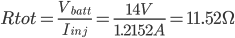
- Injector resistance. With a 14V battery voltage, I measured a 1.2152A injector current. By applying the Ohm's law, it is easy to calculate the circuit resistance (11.52Ω). This is the resistance of the complete circuit, so the injector resistance can be calculated after removing the resistance of the shunt resistor and the Rds(ON) of the MOSFET. According to this calculation, I estimated an injector resistance of 10.22Ω (this value is compatible to the Honda CBR125R datasheet, which declares an injector resistance of 8-12Ω). Of course, this value also includes the resistance of the harness cables.

- Injection time at engine idling. The injection time, during engine cold idling (1500rpm), is about 3.1-3.2ms.