In order to acquire the analog signals of Fuelino, which correspond to the analog inputs A0 - A7 of the Atmel ATmega328p microcontroller, I created a simple library which uses ADC interrupts. Since interrupts are used, the application is not locked when reading the analog input voltage. In other words, the ADC readings can be done asynchronously compared to the main software execution.
The library (ADCmgr) source code, and an example of sketch for Arduino, are fully available at the following link, on GitHub, and also here: ADC_read_analog_example_20170107m. Please check it out.
The library continuously acquires the signals on the ADC pins of the ATmega 328p. In fuelino application, not all pins (A0 - A7) are used. For example, A1 pin is used for "Slave Select" of SPI communication, and A4 and A5 are respectively SDA and SCL pins of I2C communication: the analog voltage of these pins do not need to be acquired. Input number "8" is not a physical pin, it corresponds to an internal temperature measurement available on Atmel ATmega328p.
- A0: General Purpose Digital Input (DI1)
- A2: Throttle Position Sensor
- A3: Lambda Sensor (O2 Sensor)
- A6: Battery Voltage Status
- A7: General Purpose Analog or Digital Input (ENABLE_OR_INT)
- [A8: ATmega 328p internal temperature]
Regarding the ADC acquisition frequency provided by this library, according to ATmega 328p datasheet, the ADC clock should not exceed 200kHz to avoid side effects on the accuracy, so I used 128 as prescaler value, which provides an ADC clock of 125kHz, considering a microcontroller clock of 16MHz. Each acquisition is done on a different pin, so I decided to switch ON and OFF the ADC at each acquisition: in this case, the conversion requires 25 cycles, because some cycles are necessary for ADC initialization and signal stabilization (peak and hold). Which means that, theoretically, one single acquisition can be done with a frequency of 5kHz (200 micro-seconds). However, it is necessary also to take into account the interrupt "dead" time between the end of an acquisition and the start of the next (acquisition scheduling), which causes a delay, so the practical sampling time is a bit higher, and I measured it below.
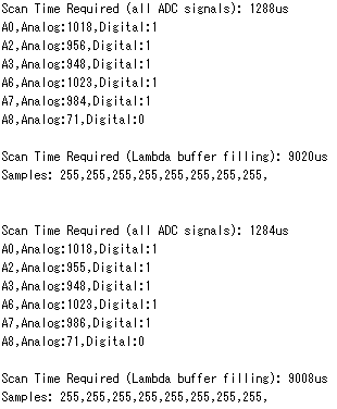
The screenshot below shows the results output by Arduino IDE Serial Monitor when the sketch is running. As shown, one complete cycle of ADC acquisitions (6 signals) requires 1284 or 1288 microseconds. During this period, all 6 inputs are measured, and then the scanning restarts from the first input. The sketch outputs both the 10 bits value (analog) and also the correspondent digital value (=1 if the signal is higher or equal than 256).
 In the library, I also implemented a useful function, to acquire signals and put them in a buffer. This is very useful for the Lambda Sensor signal. My idea is to use a fast acquisition of Lambda Sensor signal, in order to study the combustion quality (air fuel mixture): this will help fuel injection timing calibration. Basically, at each cycle (about 1288 us), the analog signal measured from the lambda sensor, is saved into a buffer of N samples (in this example, I set N = 8). In order to save memory, I decided to not use the full 10 bits scale (5V), but only 8 bits (1 byte) for each sample: in fact, a range of 0-255 should be enough to acquire the lambda sensor signal, because it corresponds to a voltage between 0V and about 1.25V. And the lambda sensor voltage is usually below 1V. This "trick" allows to save RAM memory for the buffer (1 byte instead of 2 bytes, for each sample) and SD memory space, without losing any accuracy. In case the voltage is higher than about 1.25V, "255" is saved in the buffer, so it is possible to understand when there is an over-range, when performing post processing of the data.
During my logging experiments, I noticed that the Lambda sensor voltage changes as shown below, when the motorcycle is running. At first, after Power ON, the lambda sensor voltage is about 5V, and then decreases and stabilize in the range between 0V and 1V. I suppose that this is due to the fact that the lambda sensor requires some time to stabilize (maybe the temperature).
 In the next days, I will integrate this library inside Fuelino Proto3 software, and perform some acquisitions of Lambda sensor voltage, to make sure that the air fuel mixture is correct. At first, I would like to make sure that, in engine steady state conditions (constant engine speed, constant throttle position), the air fuel ratio is correct. Therefore, I will command the buffer acquisition in such conditions. Each acquisition is done every about 1284us, and in the test above I noticed that it takes about 9020us to fill in the complete buffer (8 samples). I could increase the buffer size (for example 50 samples), which is very easy (just change a "#define" inside the library), which should correspond to a time window of about 60ms. I will save this buffer in the SD memory, together with other useful info (such as: present engine speed, throttle position signal, injection time), so that I can perform some nice post-processing of combustion mixture (air fuel ratio), using Excel or Matlab.
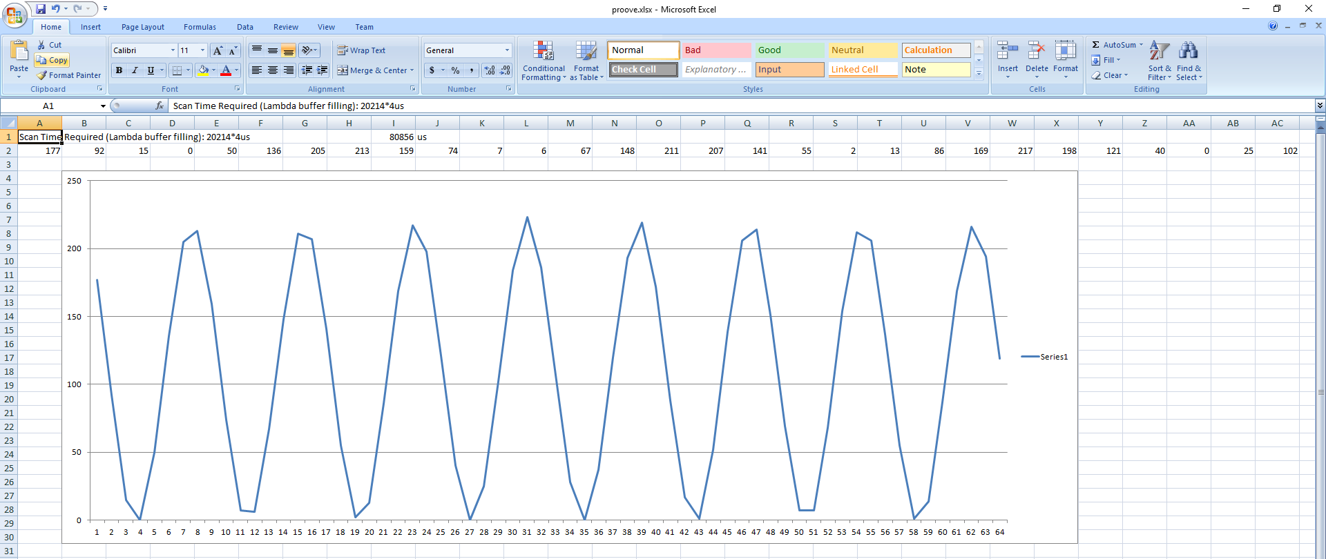
In the experiment below, I used Pico DrDaq to feed Fuelino Lambda pin with a sinus signal varying from 0V to 1V (offset: 0.5V, amplitude: 0.5V), to simulate the complete range of Lamba sensor signal. The signal has a frequency of 100Hz (period: 10ms), which corresponds to an engine rotation speed of 12000rpm.
 The following picture shows a plot of the signal output by Fuelino on Serial, when setting a buffer of 64 samples. The time required by the acquisition (from sample 0 to sample 63) is 80856us. This corresponds to a total time difference of 63 samples, therefore the average single sampling time is 1283.43us, which is coherent with the values previously measured (6 measures cycle time). As visible in the graph below, the result is quite good. The sampling time seems good enough to reconstruct the Lambda sensor signal waveform even at high rpm (12000rpm in the example). For example, using Fourier transform (example: FFT algorithm), it could be even possible to make frequency analysis on the lambda sensor signal waveform, and therefore have an additional estimation of the engine rotation speed (it should be the main frequency). And of course, it is possible to simply calculate the average voltage, which is an indicator of the correctness of the air fuel mixture. The resolution of the ADC (10 bits, 5V reference voltage) is 4.88mV, so since the maximum value in 1 byte data is 0xFF, the maximum signal which can be logged in this buffer is 1.245V. I think this is acceptable.
FuelinoToolで確認するとMAP1を選択するとIndexが0~7までありそれのThrottle[V]の各値を変更することは出来ませんか?
また、私の環境の場合Throttle[V]が0.6~4.1Vで変動するのですが、プログラムはどこを変更すればいいでしょうか?