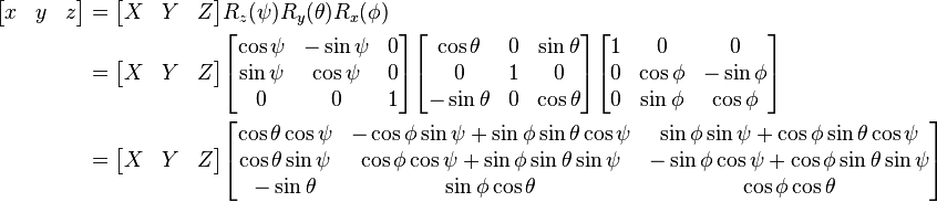
This article has the purpose of showing how it is possible to calculate Tait Bryan angles (yaw, pitch, roll) by fusing the data coming from multiple sensors (3-axis acceleration sensor and 3-axis gyroscope sensor). First of all, let's see which axis are used to evaluate the rotation angles. Please notice that axis and angles sign are related by the right-hand rule.

- Roll angle. It is the angle around X axis. A positive angle means a rotation "on the right"
- Pitch angle. It is the angle around Y axis. A positive angle means a rotation "leaning upwards"
- Yaw angle. It is the angle around Z axis. A positive angle means a rotation "on the right"
In order to calculate the rotation angles, it is possible to use accelerometer sensors signals only. However, since these sensors do not measure only the gravity component, but also acceleration, the signal is noisy. Therefore, it is necessary to evaluate also the info coming from gyroscope sensors. In addition to that, accelerometer data only is not enough to calculate the heading direction (yaw angle). On opposite, gyroscope sensors measure the angular speed (rad/s) around 3 axis, and these info must be integrated in order to calculate the orientation; in case an offset is present, the mathematical integration result error will continuously increase.
In order to fuse the info coming from both accelerometer and gyroscope sensors, I first calculate the quaternions below, and fuse them.
- Quaternion calculated using acceleration sensors signals. This quaternion is calculated starting from the rotation matrix obtained from acceleration sensors signals.

- Quaternion calculated using gyroscope sensors signals. This quaternion is calculated with mathematical integration, based on the value of the quaternion at previous integration step, and present gyroscope sensors data.


The filter fuses both quaternions and calculates the "fused quaternion", which is then used to calculate back yaw, pitch, roll angles, using the formulas below.
 The result achieved is shown in the video below. As you can see, using both data coming from acceleration sensors and gyroscope sensors helps to reduce the noise due to vibration.
The experiment is composed by 2 programs:
- One program runs on Arduino 101 and is used to acquire data from physical sensors. Data is acquired once every 1 ms. The data is then sent to the PC when the PC polls Arduino using Serial communication protocol (57600 baud). PC polls data once every 20 ms. Arduino sketch can be downloaded here: IMU_send_20160604. It uses "Curie Tempo Library" to create the 1 ms task interrupt used for sensor signal acquisition. Curie Tempo Library can be downloaded here: CurieTempo_20160604.
- PC program, created using Visual Studio Express C++ 2013. The project can be downloaded here: IMU_receive_20160604. The program contains 2 libraries: one library for Serial communication with Arduino 101, and one library "IMU.h" which contains the class (methods) used for raw sensors signal acquisition, processing and angles calculation. The results are logged on an Excel file, and also visualized in real time on the screen, using the console and Irrlicht library for 3D visualization.
This is just a starting point and the future target is to improve the performances of the fusion filter. Some improvements that I am thinking about are:
- In order to improve the estimation of yaw angle, I would like to use data coming from GPS receiver, but only when it is reliable. In particular, when the system is moving, the latitude and longitude coordinates position can be differentiated (present step position minus previous step position) in order to calculate the heading (yaw angle). This information can be fused with the yaw angle information obtained from the gyroscope quaternion. However, the fusion algorithm must take into account the reliability of each sensor (when system is moving, GPS signal is more reliable than gyroscope signal to calculate the heading, and viceversa).
- The filtering coefficient (how much the acceleration quaternion can be trusted, in comparison with the gyroscope quaternion) must take into account if the acceleration sensor data is reliable or not, and can be made time-variant. In case of no acceleration, the modulus of the 3-axis signals should be 1g (9.81 m/s2), due to the fact that only gravity force is sensed. However, when there is acceleration noise, I suppose that the modulus becomes noisy too (changing very quickly), and the modulus is not 1g anymore. These information can be used to tune, in real time, the filter coefficient. As an example, when the acceleration sensors data modulus is about 1g, only the acceleration sensors data is taken into account (filtering coefficient is about 1); on opposite, when the acceleration sensors signals are noisy, the filtering coefficient becomes about 0 (gyroscope data only is used).
- Improvement to increase calculation performance. At the moment the algorithms work using "double" precision variables. This reduces the calculation error, but increases the PC calculation load. Since the algorithm should finally run directly on the micro controller (32 bit Arduino 101), I am planning to reduce the computational cost by using "float" single precision floating point variables, and remove the non needed calculations.
Good night Davide,
I write from Brazil, and. I work with biomechanics of sport.
I loved his post "Calculating Tait Bryan angles by acceleration and gyroscope signal fusion signals".
Over time I have been looking for a tool that would allow accelerometer data and rotation angles.
I was very excited about your proposal, especially for using an arduino library that allows for acquisitions every 1 ms. That's right?
I tried to work, but I could not get the values.
Can you guide me as steps what should I do to get the values as the video example?
Can you help me ?
Hello, and thank you for your comment.
This experiment was done using an Arduino 101. Do you have the same model? Did you run the sketch on your Arduino 101?
In case you have a normal Arduino or Arduino Nano, you can use an I2C sensor module called MPU-6050, you can find it on Ebay or Amazon for just few dollars.
I also wrote a library for MPU-6050, please check the "IMU (Inertial Measurement Unit)" section of this blog.
With MPU-6050, I acquire the signal via I2C communication protocol, at 10ms. There is a low pass filter (10Hz). And the data is filtered using a digital IIR filter. After that, it is stored on the SD Memory card (or sent to the PC) once every, for example, 50 ms, which means 20 times per second (20Hz).
This allows me to calculate the orientation angle of my motorcycle while I am riding.
You are a very smart man I just want to say first off. Is there any chance you have the source code to this so I can run some tests with a project i'm working on? I hope I haven't overlooked it if it is there.
Also, I am looking to run tests not necessarily with an actual gyroscope like the arduino but with even a completely artificial data stream if that is possible. My product is moreso a proof of concept in conjunction with what you have discovered.
Thanks!
Hi Davide,
thank you for this post. We have been working with our own system and the calculation of orientation has definitely been the hardest part. I like the way you explain and execute the fusion of accelerometer and gyroscope. We do a simple 180 degree rotation test on pitch, instead of going to 180 degrees on pitch, it goes to 90 degrees back to zero then up to 90 degrees again. Could there be an error in the treatment of the signs of the accelerometer turning to negative after 90 degrees? I would really appreciate your thoughts, are you seeing the same error beyond 90 degrees?
Regards
Jamie
Hello Jamie, I know that thinking in degrees is easy for human immagnation, but I think that you should avoid it. If you want to easily handle accelerometer and gyroscope signals, you should treat them as quaternions. I suggest reading some papers online about "accelerometer", "gyroscope" and "quaternions". Basically, all calculations should be done in quaternions. Then, as output, when you want to get the yaw pitch roll, there are some formulas which let you convert quaternions into them.